
Car Ignition Coil Driver gives 15kV

The circuit described involves a high-voltage ignition coil, which is commonly used in applications such as gas engines or other ignition systems. The ignition coil transforms low voltage from a power source into a high voltage, which is necessary for creating an electric spark to ignite fuel.
To ensure safe operation, it is crucial to have a load connected to the high-voltage output of the ignition coil. This load can be a spark gap or a high-resistive load, which helps to prevent damage to the coil. Without a load, the coil may become energized without a path for the current to flow, leading to a risk of damage and potential hazards, including electrification of the coil's casing.
For applications operating at 220 or 240 VAC at 50 Hz, the circuit must be designed to handle the specific voltage and frequency. Components such as resistors, capacitors, and diodes should be selected based on their voltage ratings and power handling capabilities to ensure they can withstand the high voltages generated by the ignition coil.
Safety precautions are paramount when working with high-voltage circuits. Proper insulation and protective equipment should be utilized to prevent accidental contact with live parts. Additionally, the circuit should be housed in a non-conductive enclosure to further reduce the risk of electric shock.
It is essential to emphasize that constructing and operating this circuit is done at the builder's own risk. Adequate knowledge and understanding of high-voltage electronics are necessary to ensure safe and effective operation.This Spark Can Be Very DANGEROUS, So BE CAREFUL. WARNING: FAILURE TO DO SO: WILL CAUSE THE CASE OF THE COIL TO ALSO BE ELECTRIFIED! NOTE You MUST have a LOAD on the High Voltage Output. With NO LOAD, you have a High Risk to "Damage the Ignition Coil". Either a Spark Gap or a High Resistive Load is suitable. A 220 or 240 VAC @ 50 Hz Version is Definately Possible. Sorry but I don't have that AC power source to test one out. Lastly, If you Build this circuit, Its at your own Risk. I Will Not accept responsibility for what you do! 🔗 External reference
Related Circuits
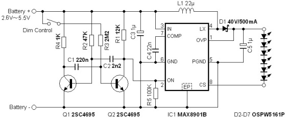
The circuit illuminates a high-brightness LED even at a voltage of 0.8V if the battery can supply 93mA at this voltage. The average step-up efficiency from 0.8V to 1.5V is 75%, with a peak efficiency of 83% occurring around...
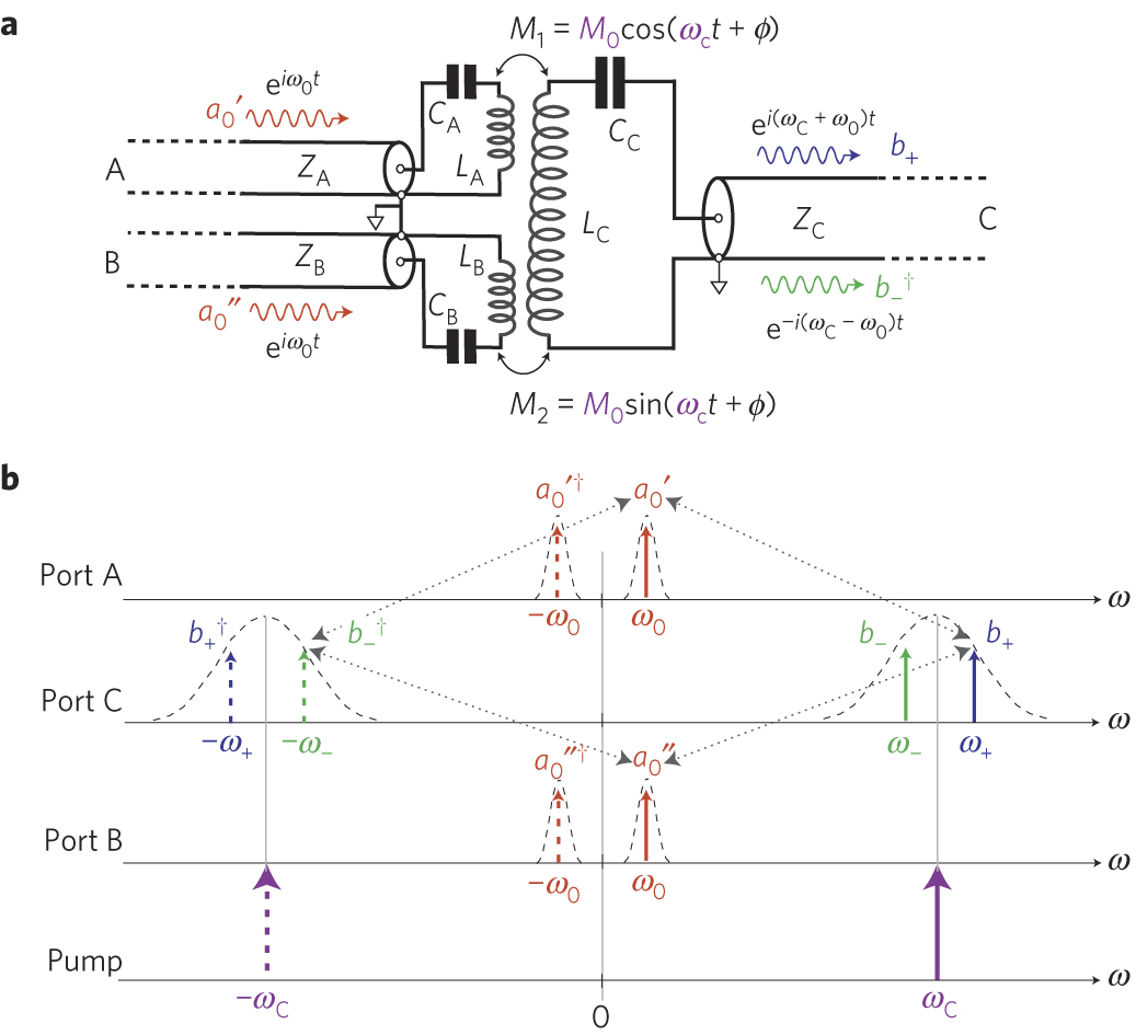
The circuit schematic of the UDC consists solely of dispersive components. Two low-frequency series LC resonators, with equal inductances (LA=LB) and capacitances (CA=CB), are connected to two input semi-infinite transmission lines, designated as A and B. These resonators are...

These circuits are commonly utilized in robotics to enable DC motors to operate in both forward and reverse directions, as well as to provide an electric brake (short circuit condition). H-bridges can be found as integrated circuits or can...
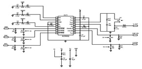
This schematic was created using a 2-layer evaluation board for the AD9662 3-Channel Laser Diode Driver. This device is primarily utilized in high-performance CD-DVD recordable drives and for laser diode current switching. The AD9662 is a specialized integrated circuit designed...
This circuit is designed to demonstrate high-frequency high voltage, capable of producing voltages up to approximately 30 kV, depending on the transformer used. It is economical and straightforward to construct, primarily utilizing a standard TV flyback transformer. The circuit...
This circuit diagram represents a radio-controlled system, commonly utilized in toy car applications for children. The circuit comprises two main components: the transmitter and the receiver circuits. The transmitter circuit generates radio signals through an oscillator circuit built with...