
Radio-controlled toy car
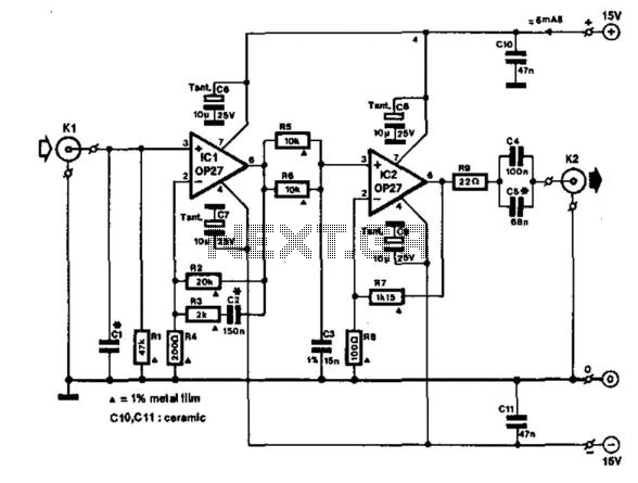
The transmitter circuit begins with the oscillator, which is responsible for generating a stable radio frequency signal. Transistor Q1 (9016) functions as the main active device in this oscillator configuration, providing the necessary gain and switching capabilities. The frequency of oscillation is finely tuned by the crystal Y1, ensuring that the emitted signals remain within the designated frequency band for radio communication.
The oscillator's performance is significantly influenced by the inductor components L1 and L2, which are carefully selected to resonate with the crystal frequency. These inductors, in conjunction with T1, form a tank circuit that is essential for maintaining the stability and purity of the oscillation. The design must ensure minimal distortion and a clean signal output, which is crucial for effective communication between the transmitter and receiver.
The receiver circuit is designed to capture the radio signals transmitted by the oscillator. It typically includes an RF amplifier to boost the received signal strength, followed by a demodulator that extracts the original control signals from the modulated carrier wave. The receiver's performance is equally critical, as it must effectively filter out noise and interference while maintaining the integrity of the control commands sent to the toy car.
The entire system is powered by a suitable DC power source, which must be regulated to ensure consistent operation of both the transmitter and receiver circuits. Proper grounding and shielding techniques should also be implemented to minimize electromagnetic interference, which can adversely affect the performance of the circuit.
Overall, this radio-controlled circuit diagram is a fundamental representation of how toy cars can be remotely operated, showcasing the essential components and their roles in the transmission and reception of radio signals. Understanding each part's function and interaction is vital for troubleshooting and enhancing the circuit's performance in practical applications.This circuit is a circuit diagram of the radio-controlled, usually in the toy car application children. Circuit diagram consists of 2 parts of the circuit sender and receiver circuits. To the circuit sending radio signals generated by the oscillator circuit formed by transistors Q1 9016, operating frequency of the oscillator is determined by the crystal Y1 is worth 27.145 MHz.
A very critical part of this oscillator circuit is T1, L1 and L2, which specifically discussed separately at the end of. 🔗 External reference
Related Circuits
This amplifier is designed to be integrated with preamplifiers that lack a phono input. A phono input is essential for standard record players equipped with dynamic pick-ups, which remain widely used. The amplifier not only elevates the output of...
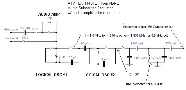
A single integrated circuit (IC) provides all amplifiers: the 74HC04 Hex Inverter, which is a digital component. The second oscillator synchronizes to three times the frequency of the first oscillator, thereby tripling the frequency modulation (FM) deviation. Utilizing the...
This simple circuit drives six LEDs in a Knight Rider scanner mode. Power consumption primarily depends on the type of LEDs used, especially when utilizing a 7555 (555 CMOS version). The Knight Rider scanner circuit is designed to create a...
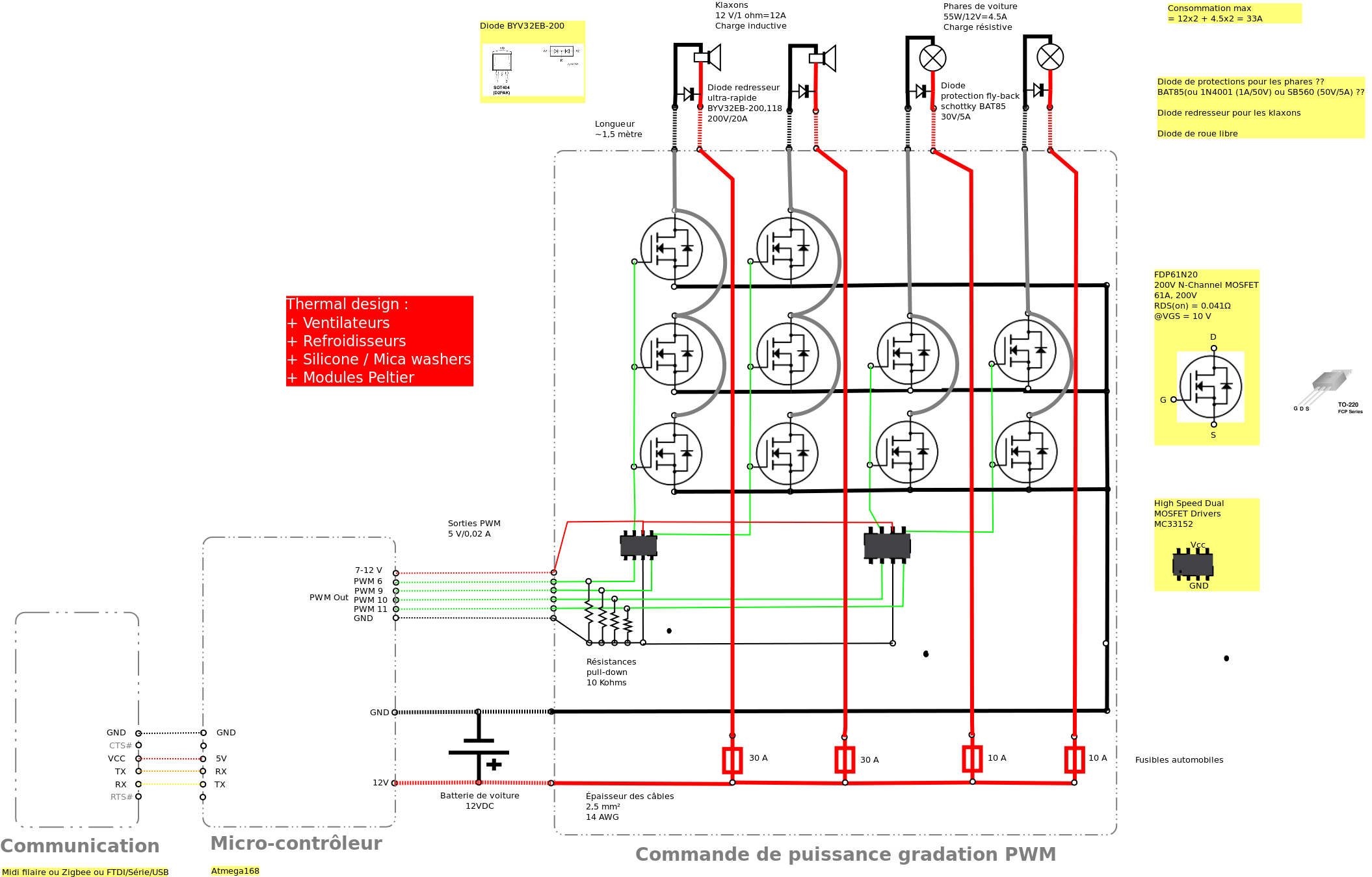
Past experiences were quite challenging due to the inductive nature of car horns, which require 12A of current, with peak demands reaching 20 to 30A. The current electronic system lacks reliability, given the high intensity. There is a need...
The project utilizes a 10 x 20 grid of RGB LEDs controlled by the myRIO. It is operated through a web interface on any device that supports WebSockets. Originally, the system was built using an Arduino, but the creator...
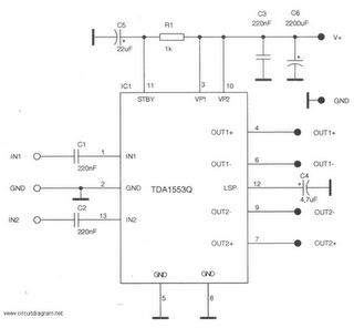
This is a 22-watt car stereo audio amplifier. The circuit is based on a single IC TDA1553 with a few peripheral components. This IC is designed for car audio applications. The TDA1553CQ integrates two 22-watt amplifiers with differential input...
Warning: include(partials/cookie-banner.php): Failed to open stream: Permission denied in /var/www/html/nextgr/view-circuit.php on line 713
Warning: include(): Failed opening 'partials/cookie-banner.php' for inclusion (include_path='.:/usr/share/php') in /var/www/html/nextgr/view-circuit.php on line 713