
Car Parking helper
Part List:
IC1=4093, R1=10Kohms 1/4W, C2=100nF 100V MKT, Q1=BC550, R2=1Mohms 1/4W, J1=2pin Connector, D1=1N4148, R3=4.7Kohms 1/4W, S1=normal open switch, D2=5mm Red normal or Flash LED, R4=820ohms 1/4W, 9V battery with clip, D3=5mm Red normal, C1=4.7uF 25V (for ~4sec delay time).
The circuit operates by utilizing a 4093 quad NAND gate integrated circuit (IC1), which functions as a timer and control unit. When the bumper of the car makes contact with switch S1, a momentary closure occurs, allowing a +9 V battery voltage to energize the circuit. This action turns on transistor Q1 (BC550), which allows current to flow through diodes D3 and D4, causing them to blink as an indication of activation.
The blinking duration is initially set to 4 seconds, determined by the time constant created by resistor R4 and capacitor C1. The capacitor charges during this period, and once fully charged, the voltage at pin 9 of IC1c transitions to a high state, while pin 10 goes low, turning off Q1 and extinguishing the LEDs. The circuit then enters a low-power standby mode, consuming minimal current until the next activation of switch S1.
The design allows for flexibility in the choice of indicator LEDs. While a Flash LED (D1) can be used, a standard 5mm LED can also be employed, providing continuous illumination for the specified duration. The time the LED remains lit can be customized by varying the capacitance value of C1; for example, using a 10uF capacitor extends the on-time to approximately 10 seconds.
The physical assembly of the circuit requires careful consideration of the switch placement to ensure it is activated appropriately by the car bumper. A protective enclosure is recommended to shield the components from moisture, which could affect performance. The LEDs should be mounted in a location that maximizes visibility to the driver, enhancing the effectiveness of the parking aid.
The part list includes all necessary components for assembly, ensuring that the circuit can be constructed with readily available parts. Proper soldering techniques and attention to detail during assembly will contribute to the reliability and functionality of the circuit in real-world applications.A simple but useful circuit for all they have problem with parking car, in spaces without good visibility. The electric circuit appears in picture 1. It is constituted by the IC1 and components round he. When the car bumper touch soft and push lightly the switch S1 then of battery voltage + 9 V it is applied in the circuit, the transistor Q1 turn ON and the diodes D3-4 they blink.
After 4 seconds the capacitor C1 charging. The pin 9 of IC1c it goes in high potential, simultaneously the pin 10 goes in low potential and Q1 turn off and the diodes turn off and the circuit it remains in situation of waiting, until the next excitation of switch S1. The consumption in the this stage remains very small, without it aggravates the battery. The use in the place of D1, Flash Led is not indispensable. Led it can replaced with one simple led 5mm, the lighting then will remain continuous for 4 seconds and then it will close. We can change the time that remains turned on the Led changing the capacity C1. With C1=10uF the time goes up in the 10 seconds. The manufacture of circuit does not have any difficulty, has however small difficulty in the mechanic manufacture and adaptation of switch S1.
A opinion of placement appears in picture 2. The circuit, the switch S1 and the battery, are placed in a box, which is not influenced easy by the humidity. The two Led can with a cable be placed somewhere highest, so that they are visible from the driver seat.
In the place of S1 can various types of switches are placed push ON with plate [see picture 3]. Suitable adaptation and extension of plate it can become as long as need. In the end of plate put a small piece of elastic, in order that when car bumper touch on him, not destroyed the colour. Part List IC1=4093 R1=10Kohms 1/4W C2=100nF 100V MKT Q1=BC550 R2=1Mohms 1/4W J1=2pin Connector D1=1N4148 R3=4.7Kohms1/4W S1=sw normal open [see Fig.
2+3 and text] D2=Led 5mm Red normal or Flash R4=820ohms 1/4W 9V battery with clip D3=Led 5mm Red normal C1=4.7uF 25V [for ~4sec delay time] 🔗 External reference
Related Circuits
This sensor circuit was designed to assist in parking a car near a garage wall while reversing. LED D7 lights up when the distance from the bumper to the wall is approximately 20 cm. LEDs D7 and D6 illuminate...
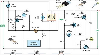
This circuit is designed to switch power to a Peltier cooler in a vehicle. Power is supplied to the load from the vehicle's battery when the ignition switch is on and from an SLA auxiliary battery when the ignition...
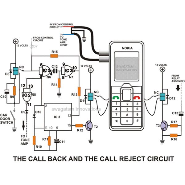
This homemade GSM car security system features a straightforward circuit design that effectively operates as a GSM car security system. The homemade GSM car security system employs a simple yet effective circuit design that integrates a GSM module, microcontroller, and...
Carrier current remote control device or intercom circuit diagram as follows: The circuit diagram for a carrier current remote control device or intercom system typically involves the use of carrier current technology to transmit audio signals over existing electrical...
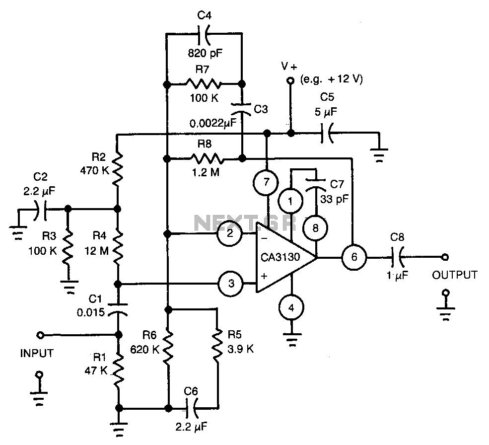
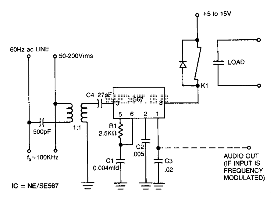
This circuit utilizes a CA3130 BiMOS operational amplifier. The amplifier is equalized to meet RIAA playback frequency response specifications. It serves as a preamplifier following a magnetic tape head. The circuit employs the CA3130 BiMOS op-amp, which combines the benefits...
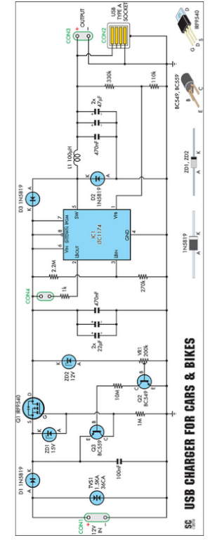
Seeking an efficient USB charger capable of operating from a 12V car battery? This unit operates at up to 89% efficiency and can charge USB devices effectively. This USB charger circuit is designed to convert a 12V car battery supply...