
In-Car Charger And Switcher Circuit For SLA Battery Circuit
This circuit operates by utilizing a combination of relays, transistors, and MOSFETs to manage power distribution effectively between the vehicle's battery and the auxiliary SLA battery. The SPDT relay serves as the primary switch, directing power to the Peltier cooler based on the ignition state, ensuring that the cooler receives power only when needed. The charging mechanism for the SLA battery is designed to optimize charging efficiency while preventing overcharging and deep discharge, which can damage the battery.
The PNP transistor Q1 plays a critical role in monitoring the SLA battery's state of charge. When the SLA battery is fully charged, the resistor R1 limits the current flow, ensuring that the battery does not receive excessive charging current. Conversely, if the SLA battery is discharged, the voltage drop across R1 activates Q1, which in turn activates MOSFET Q2 to allow charging current to flow through R2. This two-step charging process is key to maintaining battery health and longevity.
The inclusion of safety features such as the in-line fuse F1 and the PTC thermistor RT1 is essential for protecting the circuit from potential faults. The fuse provides a physical break in the circuit during a short, while the thermistor limits current during excessive load conditions, resetting automatically once the fault condition is resolved.
The low voltage disconnect mechanism ensures that the SLA battery does not reach a level that would cause irreversible damage. The voltage reference REG1 continuously monitors the battery voltage and controls the operation of Q3 and Q4 to disconnect the load when necessary. This feature is vital for preserving battery life and ensuring reliable operation of the Peltier cooler.
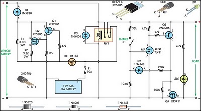
Overall, this circuit design exemplifies a robust solution for managing power to a Peltier cooler in a vehicle, integrating safety features and efficient charging mechanisms to support the auxiliary SLA battery while preventing damage and ensuring operational reliability.This circuit was devised to switch power to a Peltier cooler in a vehicle. Power to the load from the vehicle`s battery is switched by a SPDT relay while the ignition switch is turned on and from the SLA auxiliary battery when the ignition is off. The SLA battery is charged from the vehicle`s battery. When the engine is running, the voltage remain s fairly constant, which greatly simplifies the charging circuit. If the SLA battery is fully charged, any further charging current from the vehicle battery is limited by a 3. 3W 5W resistor (R1). If the SLA battery is deeply discharged, the voltage drop across this resistor will be enough to bias on PNP transistor Q1.
This will turn on P-channel Mosfet Q2 and it will provide further charging current via R2, effectively becoming a 2-step charger. Since the paralleled resistors (R1 & R2) have a lower combined voltage drop, Q1 will receive lower base bias, which in turn will cause Mosfet Q2 to fully saturate.
This positive feedback creates a clean transition between the two states and prevents Q2 from over-dissipating by being partially on. The current then will ramp down until the battery is only receiving a trickle charge and the voltage drop across the paralleled resistors is only a few dozen millivolts.
Schottky diode D1 prevents the SLA battery from discharging into the vehicle`s accessory circuits when the engine is off. Two safety devices are included in the circuit, the first being in-line fuse F1 which will prevent serious damage in case of shorts.
In addition, a PTC resettable thermistor (RT1) protects the battery from sustained over-currents during the charging phase. It is a 1. 85A hold, 3. 70A trip device at 23 °C. Since it has a positive temperature coefficient, at 70 °C, these ratings decrease to 1A and 2A for hold and trip respectively, which can further protect the battery.
Lastly, to protect the SLA battery from deep discharge, a low voltage disconnect is included. This is centred around REG1, a voltage reference configured as a comparator. Its reference (REF) input is connected to a voltage divider, as long as "enable" switch S1 is closed. Whenever the voltage at REG1`s reference terminal exceeds 2. 5V, its anode will be pulled low, biasing on PNP transistor Q3. Q3 provides positive feedback via the 270k © resistor and diode D2 to turn on N-channel Mosfet Q4, which allows the load to be powered up.
If the SLA battery voltage drops below 10V, the reference terminal will fall below 2. 5V and the anode of REG1 will go high, thereby removing bias from Q3 and turning off Q4 to disconnect the load and prevent deep discharge. LED1 indicates when power is being applied to the load. 🔗 External reference
Related Circuits
This document describes a 100 Watt inverter circuit that utilizes a minimal number of components. The circuit employs the CD 4047 integrated circuit (IC) from Texas Instruments to generate 100 Hz pulses, along with four 2N3055 transistors that drive...
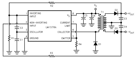
This RS232 power supply circuit diagram is a simple RS-232 line driver power supply that operates from an input voltage as low as 4.2V and delivers an output of ±12V at ±40 mA with an efficiency of better than...
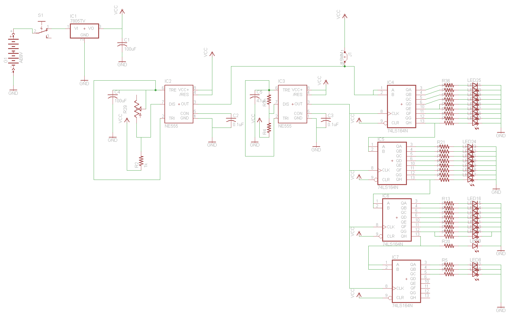
For the two-layer board schematic, six core integrated circuits (ICs) will be utilized: four 74LS164 shift registers and two 555 timers. The schematic will be constructed using the Eagle Layout Editor, as all required components are available in its...
As the position of the sun changes, the illumination level on the light-dependent resistors (LDRs) also varies, causing the input voltage for the window comparator to deviate from half of the supply voltage. Consequently, the output of the comparator...
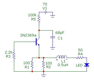
This article presents basic circuits for pulsing infrared LEDs and low-power visible semiconductor lasers utilizing inexpensive and readily available components. Numerous interesting and practical applications are referenced, alongside several online resources. The focus of the article is on the...
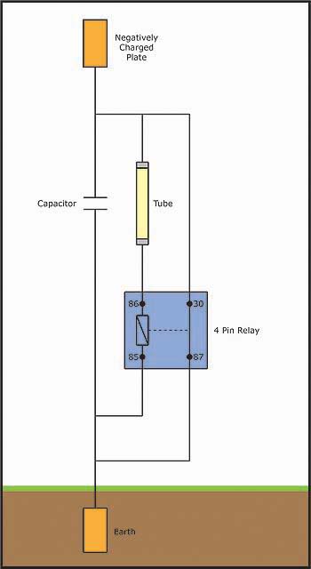
An individual has been studying Nikola Tesla's work for approximately 11 months and recently discovered Imhotep's concept of Radiant energy. The study of Nikola Tesla's contributions to electrical engineering and energy transmission has led to significant advancements in understanding electromagnetic...