car sound generator schematic
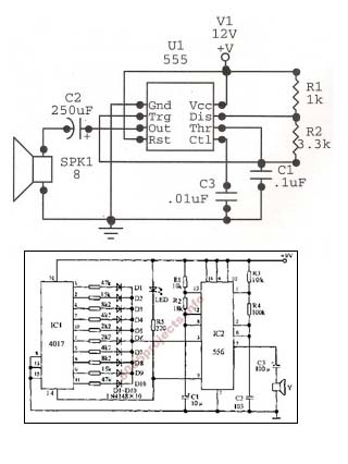
An astable oscillator is constructed using a 555 timer, producing an alarm tone of 1.8 kHz that directly drives a speaker. This fundamental alarm circuit serves as a basis for various other projects in the book. Although the circuit is designed to operate at 1.8 kHz, it can be modified for different applications by adjusting the frequency and duty cycle through the manipulation of timing components according to the appropriate formulas. Sound generation in this circuit relies on the HT2884, which can produce eight distinct sound effects, including two laser gun sounds, one dual-tone horn, two bomb sounds, two machine gun sounds, and one rifle shot. This tone generator can also be utilized for robotic control, necessitating the use of a tone decoder. To extend the frequency range, a higher or lower valued capacitor can be substituted for C1. For frequencies around 5 kHz to 15 kHz, a piezoelectric element should be used as the speaker. A miniature speaker is suitable for frequencies below 5 kHz, while an ultrasonic transducer is recommended for frequencies exceeding 30 kHz.
The astable oscillator circuit based on the 555 timer operates in a continuous oscillation mode, generating a square wave output. The frequency of oscillation is determined by the resistors and capacitors connected to the timer. The typical configuration involves two resistors (R1 and R2) and a timing capacitor (C1). The output frequency (f) can be calculated using the formula:
\[ f = \frac{1.44}{(R1 + 2R2)C1} \]
The duty cycle, which defines the ratio of the ON time to the total period of the waveform, can also be adjusted by changing the resistor values. This flexibility allows the circuit to be tailored for various applications, enhancing its utility in alarm systems and sound generation.
The HT2884 sound generator IC provides a range of audio outputs, making it suitable for applications requiring multiple sound effects. Each sound effect can be triggered through specific control signals, allowing for versatile integration into robotic systems or alarm applications. The choice of speaker components is crucial for achieving the desired sound quality and frequency response. For optimal performance, speakers should be selected based on the frequency range being utilized; piezoelectric elements are ideal for higher frequencies due to their efficiency, while miniature speakers are better suited for lower frequencies.
In summary, this astable oscillator circuit with the 555 timer and HT2884 sound generator presents a foundational design for producing alarm tones and sound effects, with adaptability for various applications through component adjustments and configurations.Here we have an astable oscillator built around 555, which gives an alarm tone of 1. 8 KHz directly driving a speaker. This is basic alarm circuit, which is later used in many other projects in the book. While the circuit shows only 1. 8 KHz operation, it can be adapted to different applications by changing frequency and duty cycle after manipulatin g the timing components as per the formula. All sounds in this circuit are generated by HT2884. There are 8 different sound effect can be produced that are 2 lazer guns, 1 dual tone horn sound, 2 bomb sounds, 2 machine gun sounds and a rifle shot sound. this tone generator can be used to control your robot. you will need to use the tone decoder for this. to widen the range, higher or lower substitute a higher, or lower valued capacitor for c1. for frequencies about 5khz and 15khz, use a piezoelectric element as the speaker. Use a miniature speaker for frequencies under 5khz, and use an ultrasonic transducer for frequencies over 30khz.
🔗 External reference
