
sound detector switch

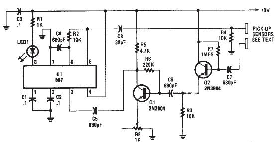
The described circuit utilizes a 555 timer IC configured in monostable mode. In this configuration, the timer is triggered by an external signal from a sound detector amplifier, which detects specific sound patterns, such as hand claps. When the sound detector outputs a signal, it triggers the 555 timer, causing the output at pin 3 to go HIGH.
The duration for which the output remains HIGH is determined by the resistor R2 and capacitor C2. The time period (T) for the monostable operation can be calculated using the formula:
T = 1.1 × R2 × C2
Where T is in seconds, R2 is in ohms, and C2 is in farads. The circuit allows for fine-tuning of the timing duration by adjusting R1, which is connected in series or parallel to R2, depending on the desired adjustment mechanism. This flexibility enables the circuit to listen for hand claps over a range from 10 seconds down to 0.2 seconds, making it versatile for various applications.
The components specified in the circuit design adhere to standard tolerances. All resistors are rated at either 5% or 10% tolerance, ensuring reliable performance within acceptable limits, and are rated for 1/4 watt to handle the power dissipation safely. The capacitors utilized in the circuit are 10% tolerance and rated for 35 volts or higher, providing adequate voltage headroom for the operation of the 555 timer and ensuring stability during the timing cycle.
This circuit can be implemented on a breadboard for prototyping or designed into a PCB for more permanent applications, allowing for integration into systems that require sound detection and response functionalities. Proper attention to component ratings and tolerances will ensure the longevity and reliability of the circuit in practical applications.When the 555 ic goes into timing mode (triggered by an output signal from the sound detector amplifier,) the timer`s output (pin 3) is set into HIGH for a duration set by C2, and R2. adjusting R1 will adjust how long it listens, from 10 seconds all the way down to 2/10ths of a second.
this could be used to listen for hand claps. all resistors are 5 or 10 percent tolerance, 1/4-watt all capacitors are 10 percent tolerance, rated 35 volts or higher 🔗 External reference
Related Circuits
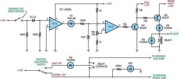
The current vehicle, a Pajero, has been modified for dual fuel operation, utilizing both petrol and gas. It is essential to operate the vehicle on petrol at regular intervals to prevent clogging of the injectors. This circuit facilitates starting...
Men often appreciate the convenience of television remote controls, which can sometimes frustrate their female partners. They tend to switch channels frequently, wanting to ensure they do not miss anything while a specific program is on. With the remote...
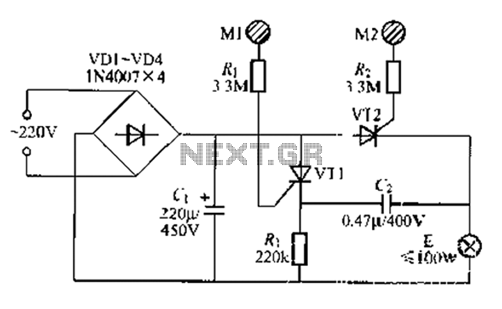
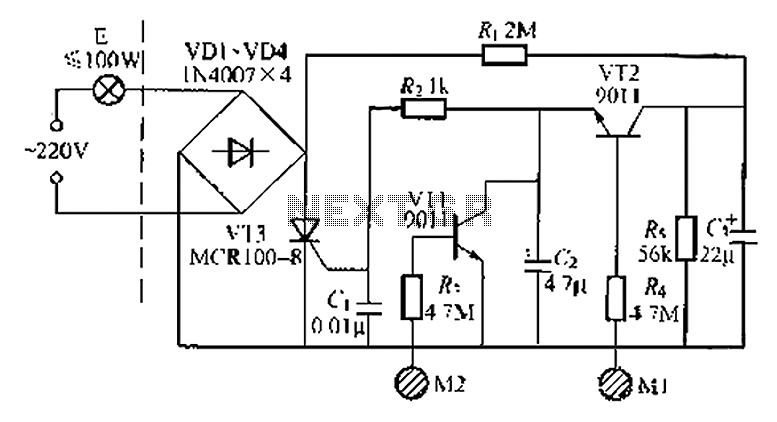
A circuit configuration features a relatively new strong key touch-state switch. Normally, the thyristors VT1 and VT2 are in the off-state, allowing minimal current to pass through the lamp F. At this point, the capacitance C comes into play....
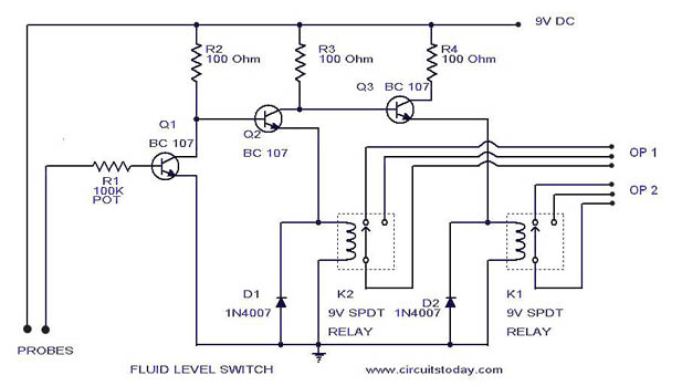
A simple liquid level switch circuit with diagram and schematic. This can also be used as a water level switch, fluid level switch, float level switch, and tank level switch. The liquid level switch circuit is designed to detect the...
A simple proximity detector electronic project can be designed using this schematic circuit. This project utilizes a tone decoder integrated circuit (NE567), which provides a signal with a frequency of approximately 100 kHz. When an object is placed near...
A good performance is achieved with a two-wire connection for a double touch switch that can function even if there is a break in the left part of the line. This switch is designed for general lighting control, such...