
Audio Sound Effects Circuit
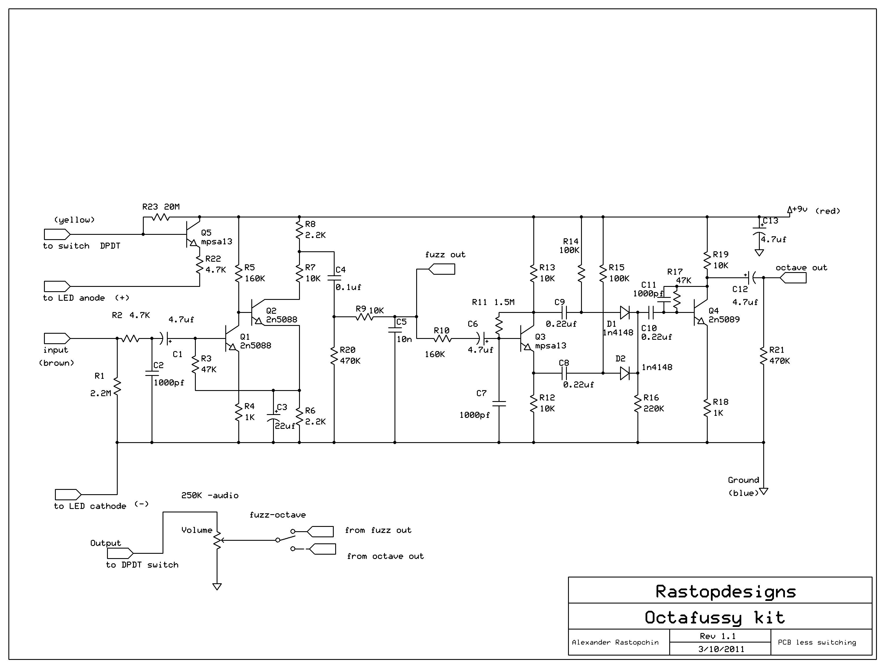
The sound effects circuit operates by manipulating the input audio signal from the electric guitar, introducing non-linearities that result in distortion. The primary components of this circuit typically include operational amplifiers (op-amps), diodes, resistors, and capacitors.
The circuit begins with the input stage, where the guitar signal is fed into a buffer amplifier. This buffer prevents loading effects that could alter the sound characteristics. Following this, the signal is directed to a distortion stage, which often employs an op-amp configured in a non-inverting mode. The gain of this stage can be adjusted using a variable resistor, allowing users to control the level of distortion.
Diodes are commonly used in the feedback loop of the op-amp to clip the signal peaks, creating the desired distortion effect. The choice of diodes can significantly affect the tonal characteristics, with silicon diodes producing a sharper clipping compared to germanium diodes, which yield a warmer sound.
After the distortion stage, the signal may pass through a tone control circuit consisting of capacitors and resistors that shape the frequency response, allowing users to enhance or attenuate specific frequencies. Finally, the output stage may include another buffer to drive the output signal to an amplifier or effects chain without degradation.
This circuit can be housed in a compact enclosure with input and output jacks, a power supply connector, and control knobs for gain and tone adjustments, providing musicians with a versatile tool for enhancing their sound. The design can be adapted with additional features such as a bypass switch, LED indicators, or even a built-in reverb effect, making it a valuable addition to any guitarist's setup.This sound effects circuit is designed to work as a signal distorter. If used with an electric guitar, it allows the production of special sound effects. T.. 🔗 External reference
Related Circuits
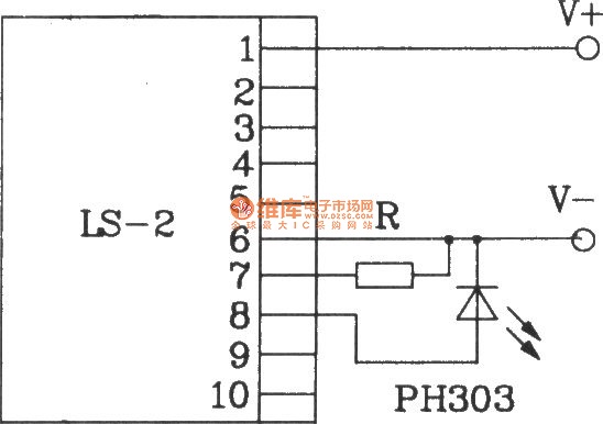
The LS-2 remote control switch infrared sensor module is similar to the LS-18 but functions as a reflector. The LS-2 pin diagram and internal block diagram provide insights into its electrical parameters. The operating voltage for the LS-2 remote...
The circuit employs two Light Dependent Resistors (LDRs) arranged in series with a separation of approximately half a meter. This configuration allows each LDR to detect the presence of a person entering or exiting the room. The processed outputs...
After testing various circuits, the simplest design was developed, characterized by minimal parts count and straightforward signal flow, reminiscent of "Heathkits." This design features a single tone control and an FET buffer. Modern elements include True Bypass switching, a...
The circuit is a DC to DC converter utilizing a standard 12 VAC center-tapped power transformer configured as a blocking oscillator. Although the circuit exhibits low efficiency, it generates a high voltage suitable for low-power applications. The input battery...
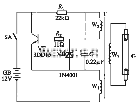
A self-excited transistor inverter circuit is designed for improved performance and features a relatively simple schematic. It is suitable for driving fluorescent lamps with a power rating between 8 to 40 watts. This inverter can operate stably even when...
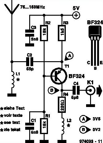
This inexpensive FM radio receiver antenna booster utilizes the BF324 TO92 style PNP transistor in a grounded-base configuration. The circuit can be employed as a... The FM radio receiver antenna booster circuit is designed to enhance the reception capabilities of...
Warning: include(partials/cookie-banner.php): Failed to open stream: Permission denied in /var/www/html/nextgr/view-circuit.php on line 713
Warning: include(): Failed opening 'partials/cookie-banner.php' for inclusion (include_path='.:/usr/share/php') in /var/www/html/nextgr/view-circuit.php on line 713