
Car water Temperature monitor

The Car Temperature Gauge circuit is designed to measure and display the engine coolant temperature with high precision, specifically to a resolution of 1 degree Celsius. The core components of this circuit include a temperature sensor, typically a thermistor or an LM35 temperature sensor, which converts the temperature into an electrical signal.
The circuit utilizes an analog-to-digital converter (ADC) to translate the analog voltage signal from the sensor into a digital format suitable for processing. The ADC's output is then fed into a microcontroller, which processes the data and drives a display module, such as an LCD or LED display, to present the temperature reading.
In terms of the input circuit modifications referenced, these may involve adjustments to the sensor interface, such as adding filtering capacitors to reduce noise, or implementing a voltage divider to ensure that the sensor's output voltage remains within the ADC's input range. The microcontroller may also include calibration routines to account for sensor inaccuracies, ensuring that the displayed temperature is accurate.
Power supply considerations are crucial in this design, as the circuit should operate reliably under varying conditions. Typically, a voltage regulator may be employed to provide a stable voltage supply to the microcontroller and sensor, protecting the components from voltage fluctuations.
Overall, this Car Temperature Gauge circuit is a practical implementation of temperature measurement in automotive applications, providing real-time feedback to the driver and contributing to vehicle safety and performance monitoring.The Car Temperature Gauge is basically the same circuit as March's project with some minor changes to the input circuit. This circuit will display the water temperature to 1 degree resolution. 🔗 External reference
Related Circuits
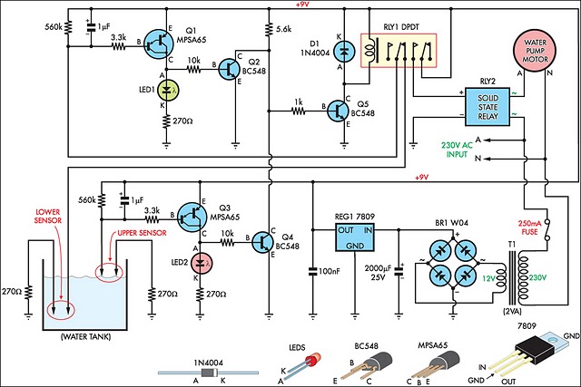
This circuit is designed to efficiently fill a header tank for a reticulated water supply on a farm. It supplies eight troughs located in various paddocks where water scarcity can have severe consequences for livestock. Previously, the tank was...
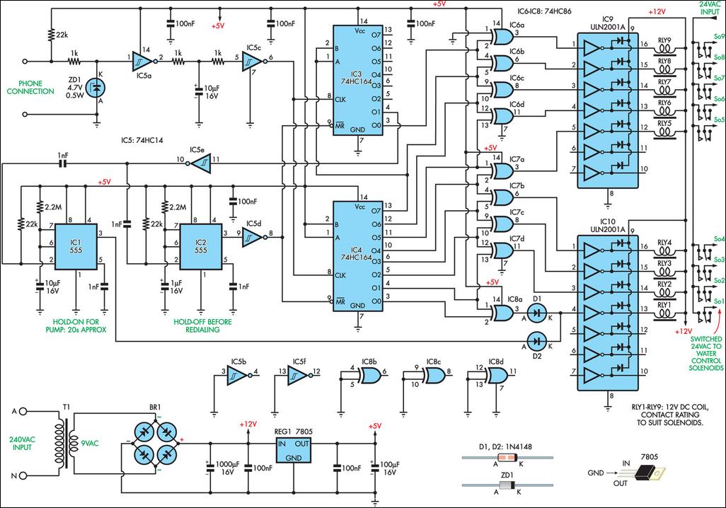
This remotely controlled watering system is cost-effective and easily expandable. It operates in conjunction with a conventional watering timer, enabling remote switching between nine zones. The prototype is designed for use with a bore system, where a deep-well pump...
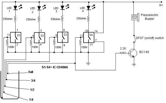
A low-cost water level indicator circuit can be designed using this schematic. This water level indicator utilizes a CMOS IC, the CD4066, to indicate the amount of water present in an overhead tank and provides an alarm when the...
This circuit utilizes the widely available LM3914 integrated circuit (IC). The IC is straightforward to operate, does not require external voltage regulators due to its built-in voltage regulation feature, and can be powered from nearly any voltage source. The LM3914...

When the water level is low, the wires in the tank are open-circuited, causing the 180K ohm resistor to pull the switch low, resulting in the switch being open and the LEDs being off. As water begins to fill...
The electric car remote control circuit diagram enables the model car to move forward and backward, as well as turn left and right. It is simple and easy to operate. The radio remote control receiver demodulation circuit utilizes TWH9238...