
Inexpensive Remote Watering System
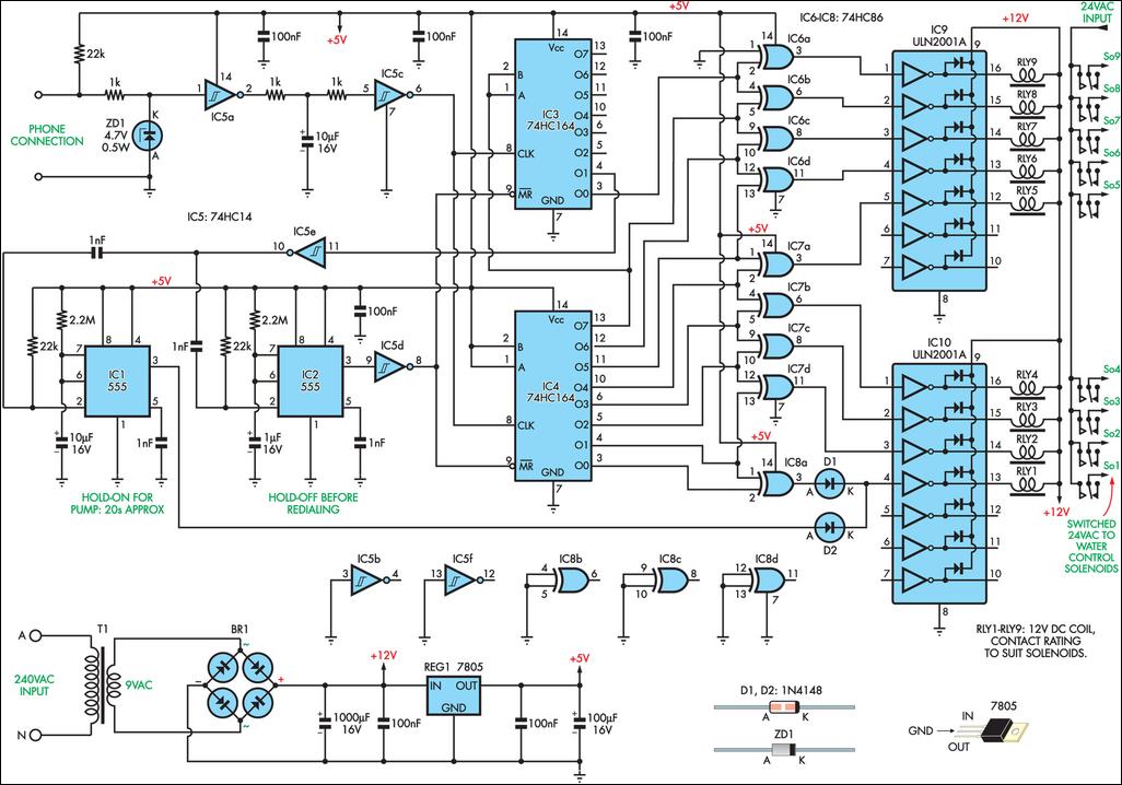
Examining the circuit, the telephone base station is connected to one input of a hex Schmitt-trigger inverter (IC5a), which acts as a low-pass filter and pulse shaper in conjunction with two 1kΩ resistors, a 10 µF capacitor, and a second inverter (IC5c). Glitch-free pulses are directed to the clock inputs of two 74HC164 8-stage shift registers (IC3 & IC4). The A & B inputs of IC4 are permanently pulled high, causing the first pulse to yield a logic high at output O0 (pin 3). Each subsequent pulse triggers the next output to go high. After eight pulses, output O7 (pin 13) becomes high and propagates to the second shift register (IC4) via its A & B inputs. The outputs of the shift registers are connected to a series of 74HC86 exclusive-OR gates (IC6-IC8), ensuring that only one output from the 74HC86 can be high at any given time. For example, after three clock pulses, outputs O0-O3 of IC4 will be high, resulting in a high output from IC7c.
The exclusive-OR gates drive a pair of ULN2001A Darlington drivers (IC9 & IC10), which control relays to switch power to the water solenoids. If an incorrect key is pressed at the remote end and 10 pulses reach the shift register inputs, output O1 of IC3 will go high, activating both 555 timers (IC1 & IC2) through inverter IC5e. The 555 timers are configured as monostables, causing their outputs to immediately swing high. IC2 resets the shift registers, returning all outputs to their initial low state. This reset signal is maintained for approximately three seconds, ensuring that any additional pulses beyond the maximum of nine are disregarded. Meanwhile, IC1 energizes one of the water solenoids via diode D2 and the zone #1 driver circuit. This solenoid remains activated for about 20 seconds, allowing sufficient time for the number to be redialed following the three-second redial "hold-off" period. This hold-on period is crucial to prevent overheating of the pump motor, which could occur without continuous water flow.
The circuit operates from a +5V supply, generated by a conventional bridge rectifier (BR1), filter, and regulator arrangement. The 24VAC required for the water solenoids is sourced from the water system timer transformer, which is external to this circuit. For the "sorry, wrong number" feature to function effectively, some form of operator feedback is necessary, especially if all sprinklers are not visible. A siren could be activated by IC1's output to alert the operator that a valid sector number must be dialed within 20 seconds.This remotely controlled watering system is both inexpensive and easy to expand. It is designed to operate in conjunction with a conventional watering timer and allows remote switching between nine zones. The prototype is used in a bore system, where a deep-well pump must be started and kept running while zones are being changed.
This is necessary to minimise cycling and results in maximum pump life. A standard portable telephone is used as the transmitter and receiver. The system`s range is therefore limited only by the telephone specifications. The prototype uses an Audioline model CDL1A, set to pulse-dial mode via a switch in the side. Selecting zones from the telephone keypad couldn`t be simpler. For the first nine zones, each key number (1-9) corresponds directly to a zone number. If additional zones were added to the basic circuit, "0" would represents zone 10, while further zones are "dialed-in" by simple addition. For example, to select station 15, you`d press "0" and then "5". Looking now at the circuit, the telephone base station is wired to one input of a hex Schmitt-trigger inverter (IC5a), which functions as a low-pass filter and pulse shaper in conjunction with two 1kO resistors, a 10 µF capacitor and a second inverter (IC5c).
Glitch-free pulses are fed to the clock inputs of two 74HC164 8-stage shift registers (IC3 & IC4). The A & B inputs of IC4 are permanently pulled high, so the first pulse results in a logic high at output O0 (pin 3). Each additional pulse causes the next successive output to go high. After eight pulses, output O7 (pin 13) goes high and this is propagated to the second shift register (IC4) via its A & B inputs.
The shift register outputs are wired to a collection of 74HC86 exclusive-OR gates (IC6-IC8) in such a way that only one of the 74HC86 outputs can be high at a time. For example, after three clock pulses, outputs O0-O3 of IC4 are high, which results in IC7c`s output going high.
The exclusive-OR gates feed a pair of ULN2001A Darlington drivers (IC9 & IC10), which in turn drive relays to switch power to the water solenoids. If a wrong key is pressed at the remote end and 10 pulses arrive at the shift register inputs, output O1 of IC3 will go high, triggering both 555 timers (IC1 & IC2) via inverter IC5e.
The 555s are configured as monostables, so their outputs immediately swing high. IC2 resets the shift registers, returning all outputs to their initial (low) state. The reset signal is held for about three seconds, which ensures that any number of additional pulses (within reason) above the maximum of nine will be ignored. In the meantime, IC1 energises one of the water solenoids via diode D2 and the zone #1 driver circuit.
This solenoid is held on for about 20 seconds, giving sufficient time for the number to be redialled after the 3-second redial "hold-off" period. This solenoid "hold-on" period is important as it prevents overheating of the pump motor that might otherwise occur without continuous water flow.
The circuit operates from +5V, which is generated by a conventional bridge rectifier (BR1), filter and regulator arrangement. 24VAC for the water solenoids is obtained from the water system timer transformer and is external to this circuit.
For the "sorry, wrong number" feature to be effective, some form of operator feedback would be required if all of the sprinklers are not visible. Perhaps a siren could also be driven by IC1`s output to alert the operator that a valid sector number must be dialled within 20 seconds!
🔗 External reference
Related Circuits

The circuit depicted in the schematic utilizes zero-drift operational amplifiers (LTC1250 and LTC1050) along with a precision instrumentation switched capacitor block (LTC1043). This design achieves exceptional DC accuracy down to microvolt levels. The choice of this method over a...
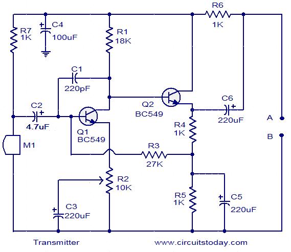
The circuit schematic illustrates a simple audio surveillance system in which the transmitter captures sound from one location, while the receiver reproduces it at another location. Both the transmitter and receiver are connected by a single wire, which carries...
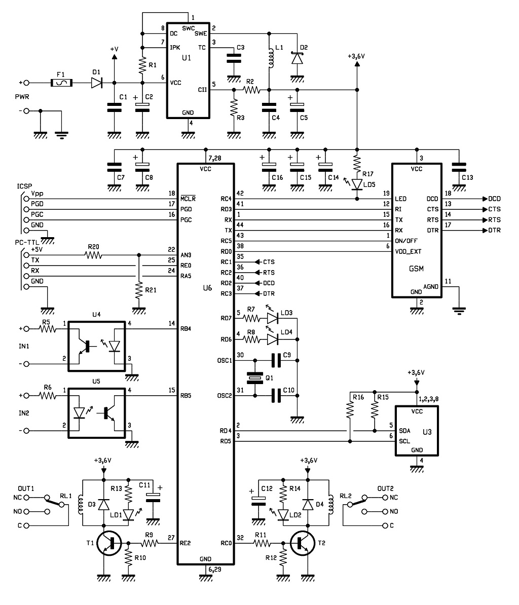
The control of the system is managed by a Microchip PIC18F46K20-I/PT microcontroller, which is programmed with firmware to oversee the activity of the GSM/GPRS module, monitor the logic conditions of two opto-isolated inputs, and send commands to two relays...
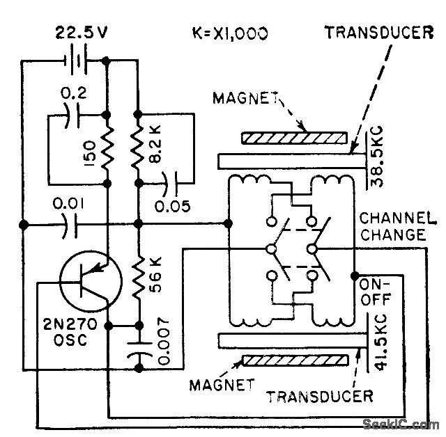
The frequency of a transistor oscillator is regulated by two different lengths of nickel tubing, each containing two coil windings. One coil functions as a driver, while the other serves as a pickup to generate feedback voltage necessary for...
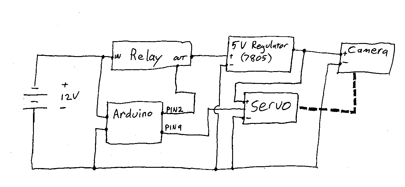
Information and resources on remotely using a DSLR camera, primarily utilizing Arduino-based solutions. The use of Arduino-based systems for remotely controlling DSLR cameras has gained popularity among photography enthusiasts and professionals seeking to enhance their shooting capabilities. These systems typically...
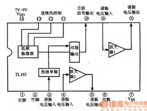
The following circuit illustrates the TL163 integrated circuit (IC) used in an ultrasonic remote control circuit diagram. Features include a detector, high-gain amplifier, and low-frequency response. The TL163 IC is designed to facilitate ultrasonic signal processing, making it suitable for...