
Automatic Water Tank FillerCircuit Circuit
The circuit utilizes a combination of sensors and transistors to create an automated water level control system that enhances the reliability of water supply for livestock. The use of Darlington transistors allows for high current amplification, ensuring that the control signals can effectively manage the operation of the pump. The NOR gate configuration enables a simple yet effective logic operation, where the output only activates the pump when both sensors indicate a low water level.
The relay system provides a robust method for isolating the control circuit from the high-power components, such as the submersible pump. This isolation is crucial for protecting sensitive electronic components from voltage spikes and current surges that occur during the pump's operation. The solid-state relay (RLY2) is particularly well-suited for this application due to its ability to handle the inductive load of the pump without mechanical wear, thereby enhancing the longevity and reliability of the system.
The placement of the sensors is strategically designed to prevent overflow and ensure that the tank is adequately filled before reaching critical low levels. The use of stainless steel screws as sensor contacts offers durability and resistance to corrosion, which is essential in a water application. Furthermore, the sealing of wiring junctions with silicone sealant prevents moisture ingress, contributing to the overall reliability of the circuit in outdoor conditions.
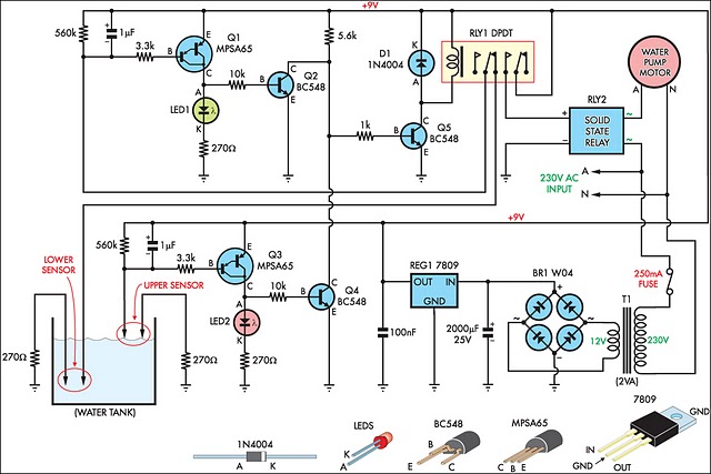
Overall, this circuit design exemplifies an effective solution for maintaining water supply in agricultural settings, addressing the challenges posed by variable weather conditions and livestock demands.This circuit has been very useful in filling a header tank for a reticulated water supply on a farm. Eight troughs are supplied in different paddocks where a lack of water would have serious consequences for the stock. In the past, the tank had been filled daily by a time clock which was not successful. During hot weather, the stock would empty th e tank on a regular basis and then be without water for several hours or the tank would overflow and flood the area if the weather was wet and the cattle did not drink much. The circuit described has been used to maintain the level of water in the header tank within prescribed limits.
It controls a 3HP submersible bore pump which has a high starting current, necessitating a solid-state relay sufficient to take the starting load. Two Darlington transistors, Q1 & Q3, in conjunction with Q2 & Q4, are connected to the upper and lower water sensors in the tank.
Q2 & Q4 have a common 5. 6kO load resistor and function as a NOR gate. The output of the NOR gate drives Q5 which activates relay RLY1. Initially, when the water level is low, both sensors will be open-circuit, the NOR gate output will be high and the relay will be turned on. This causes the normally closed (NC) contacts of the relay to open and disconnect the lower sensor. However, the upper sensor will still be open circuit and the NOR gate output will be high, keeping the relay closed.
The normally open (NO) contact of the relay will be closed to operate the solid-state relay RLY2 to run the pump. This state continues until the water reaches the top sensor which will then drop the output from the NOR gate to 0V.
The disables relay RLY1 and the pump is stopped. In practice the upper level sensor is just below the overflow from the tank and the lower sensor about half way up the tank. The sensor contacts are simply two stainless steel screws about 25mm apart and screwed through the poly tank walls.
The wiring junctions on the side of the tank are protected by neutral-cure silicone sealant. 🔗 External reference
Related Circuits
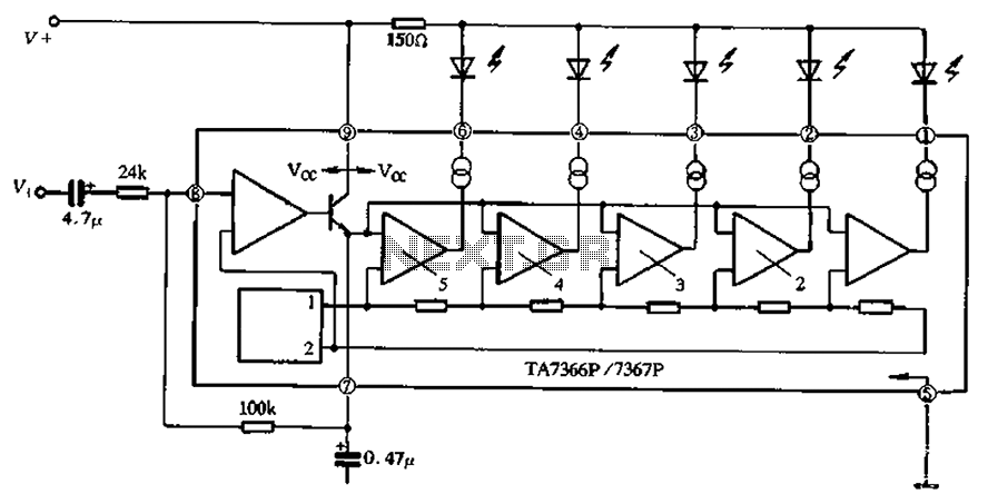
The TA 7366/7367 is a commonly used single display driver circuit manufactured by Toshiba Corporation. It features a 5 LED driver circuit and is designed in a 9-pin single in-line plastic structure. The circuit configuration includes an operational amplifier...
The voltage to be sampled is applied to the input of R2, a 100K linear taper potentiometer, while the other end of R2 is grounded. Consequently, the signal level that is sent to the buffering level shifter U1-A and...
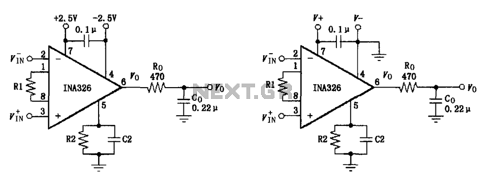
The basic connection circuit for the INA326/327 includes signals and power. A 0.1 µF capacitor is selected for power supply filtering and should be placed as close to the chip's supply pin as possible. Ro and Co serve as...
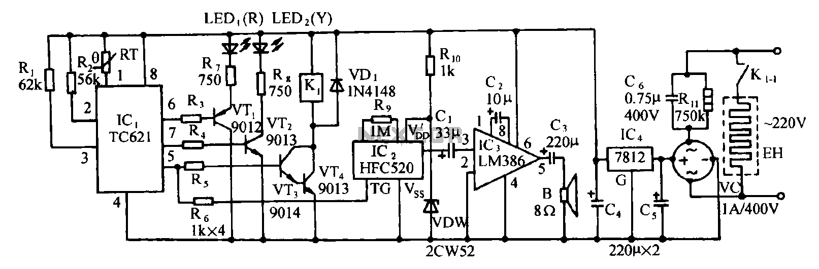
Eggs hatch chicks at temperature requirements within the range of 36 to 39 degrees Celsius. The temperature sensor integrated circuits utilize the TC621 temperature control circuit, which has fewer external components, is low cost, and offers high reliability. Users...
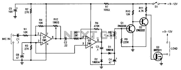
This audio-controlled switch integrates a pair of 741 operational amplifiers, two 2N2222 general-purpose transistors, an hcxFET, and several supporting components into a circuit capable of activating devices such as a tape recorder, a transmitter, or virtually any sound-activated equipment. The...
This circuit deactivates an amplifier or any connected device when a low-level audio signal at its input is absent for at least 15 minutes. By pressing P1, the device is powered on, supplying power to any appliance connected to...
Warning: include(partials/cookie-banner.php): Failed to open stream: Permission denied in /var/www/html/nextgr/view-circuit.php on line 713
Warning: include(): Failed opening 'partials/cookie-banner.php' for inclusion (include_path='.:/usr/share/php') in /var/www/html/nextgr/view-circuit.php on line 713