
Carport wireless alarm circuit a
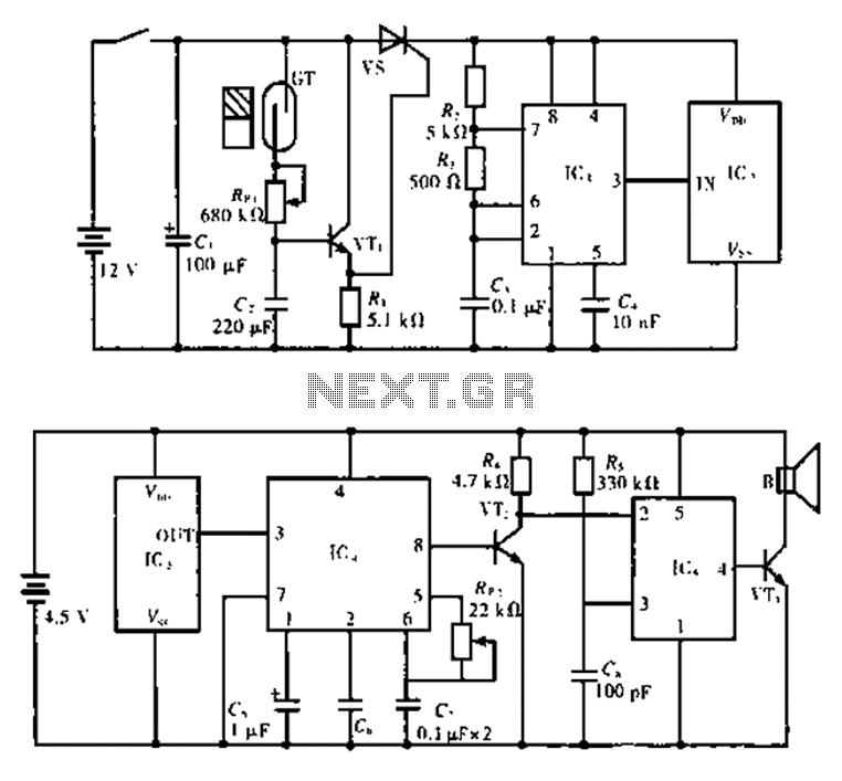
The alarm circuit functions by utilizing the interaction between the transmitter and receiver to detect smoke or unauthorized access. The transmitter's core component, the GT reed switch, operates as a sensor, responding to the presence of a magnetic field. When the magnet is sufficiently close, the switch opens, triggering the 555 timer circuit (IC1).
The 555 timer is configured in a monostable mode, where it generates a pulse with a duration determined by the values of R2, R3, and C3. This pulse serves as a trigger for the subsequent components of the circuit. The multivibrator configuration produces a continuous square wave oscillation at 1 kHz, which is then fed into the T630 transmitting circuit (IC2).
The T630 circuit is designed to modulate the 1 kHz signal into a 150 kHz carrier wave, suitable for transmission. This process involves pulse modulation, which encodes the information from the 555 timer onto the carrier frequency. The output of IC2 is then transmitted via the built-in antenna, allowing the signal to be sent over a distance to the receiver unit.
The receiver, not detailed in the initial description, would typically include a matching antenna to capture the transmitted signal, followed by a demodulation stage to retrieve the original 1 kHz signal. Upon detecting the signal, the receiver can activate an alarm or alert system, indicating the presence of smoke or an unauthorized entry.
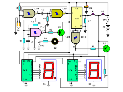
This alarm system is widely applicable in various safety and security scenarios, providing an effective means of monitoring environments for smoke or intrusion. The careful selection of components and their configuration ensures reliable operation and responsiveness to potential hazards. Circuit for the principle: The alarm circuit consists of two parts, the transmitter and receiver. Figure a shows the transmitter circuit, GT is a smoke break reed switch, usual ly shed door when the magnet close to the GT, GT inside contacts open. lC1 is 555 circuits, and R3, R2, C3 constitute self-excited multivibrator, the oscillation frequency of 1 kHz. lC2 is built-in antenna type transmitting circuit T630, contains an internal pulse modulation, amplification shaping, firing several parts circuit, operating frequency is 150 kHz.
Related Circuits
This infrared transmitter utilizes pulse width modulation (PWM). The transmitter is equipped with an LM567 tone decoder circuit. An audio signal (at least 50 mV peak-to-peak) is amplified with transistor T1 and subsequently used to modulate IC1. The frequency...
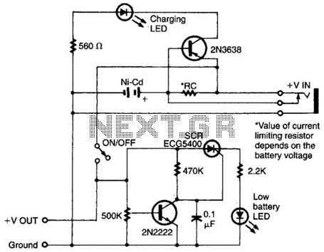
Intended for a NiCad application, this charging circuit can be used with a wide range of batteries. A low-battery detector is included, and the trip voltage is set via a 500 kΩ potentiometer. Select the resistor for the battery...
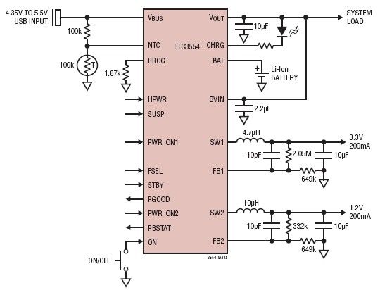
This micropower multifunction power management integrated circuit (PMIC) is designed using the LTC3554, manufactured by Linear Technology Corporation. It serves as a solution for portable Li-Ion Polymer battery-based applications. The LTC3554 integrates a USB-compatible linear PowerPath manager, a standalone...
This circuit measures the distance covered during a walk. The hardware is housed in a small box that can be placed in a pocket, and the display is designed as follows: the leftmost display D2 (the most significant digit)...
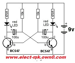
Robot eyes circuit of Service. A simple circuit to simulate a man appointed to it. It consists of a dual-lamp working in an unsteady manner. Circuit diagram. The robot eyes circuit is designed to create a visual effect that simulates...

This is a circuit design for a PWM speed control circuit for DC motor rotation. The circuit features two functions: Forward-Reverse operation and Regenerative Braking. The control is achieved using a MOSFET. The circuit allows for the control of...