
Infrared transmitter circuit schematic
The infrared transmitter circuit operates on the principle of pulse width modulation (PWM) to encode audio signals for wireless transmission. The LM567 tone decoder serves as a critical component, enabling the detection of specific frequencies, which enhances the system's ability to filter out noise and improve signal integrity. The audio input, which must meet a minimum amplitude of 50 mV peak-to-peak, is first amplified by the transistor T1. This amplification stage is essential to ensure that the audio signal is sufficiently strong for effective modulation.
The modulation is performed by IC1, which is responsible for converting the amplified audio signal into a modulated infrared signal. The frequency of this modulation can be fine-tuned using the adjustable potentiometer P2, allowing for flexibility in the operating frequency of the transmitter. This adjustment capability is crucial for optimizing performance in various environments and applications.
The circuit also includes additional components such as the EPM7128STC100-15, which is a field-programmable gate array (FPGA) that can be used for further processing or control functions within the system. The DG413DY is a dual analog switch that may be utilized for routing signals within the circuit, while the AD620AR is an instrumentation amplifier that can enhance the signal conditioning stage, ensuring that the audio signal is clean and accurately represented before modulation.
Overall, this infrared transmitter circuit is designed for efficient audio signal transmission using infrared light, making it suitable for various applications, including remote controls, wireless audio systems, and other communication devices that require reliable and effective signal transmission.This infrared transmitter use PWM, pulse width modulation The transmitter is equiped with LM 567, tone decoder circuit. Audio signal ( at least 50mVvv ) is amplified with T1 and then it is used to modulate IC1. Infrared transmitter frequency is adjusted with P2 between 25 and 40KHz. IR transmitter circuit diagram EPM7128STC100-15 DG413DY AD620AR. 🔗 External reference
Related Circuits
This is a convenient design for a transistor tester. The advantage of this circuit is that transistors can be tested without actually doing the circuit soldering. The tester uses two ICs: an NE 555 timer and a CMOS IC...
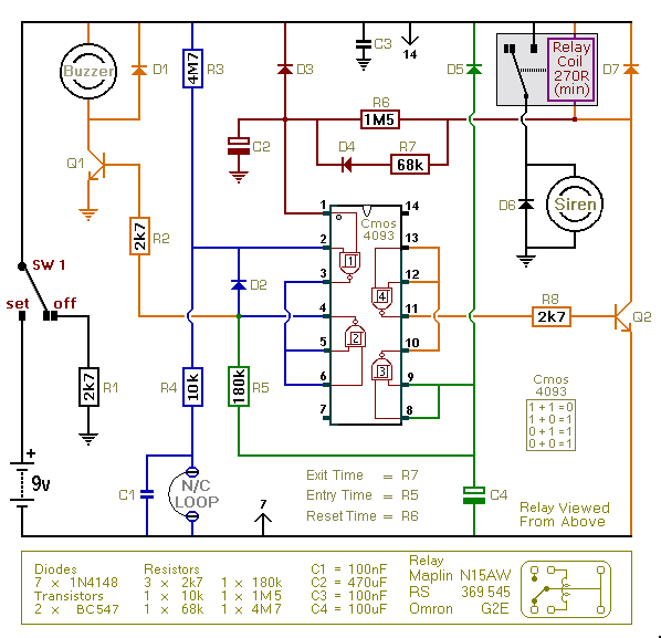
This is an improved version of the basic Garage/Shed Alarm. The Entry and Exit delays have been extended to approximately 30 seconds, and a timed Siren cut-off along with an automatic reset feature has been added. Additionally, the LED...
A high voltage power supply is a valuable source that can be effectively used in various applications, such as biasing gas-discharge tubes and radiation detectors. This type of power supply can also serve as a protective measure, such as...
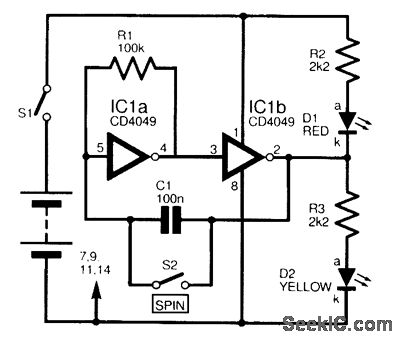
This circuit is designed to electronically simulate the tossing of a coin using a 4049 hex inverter integrated circuit (IC). It employs two of these ICs, specifically IC1a and IC1b, which are configured as an astable oscillator. This configuration...
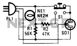
If residing in a cold climate, it is reassuring to confirm the functionality of an engine-block heater. This device indicates whether the heater is operational. To use, connect PL1 to a power outlet; the NE1 indicator should illuminate. Next,...
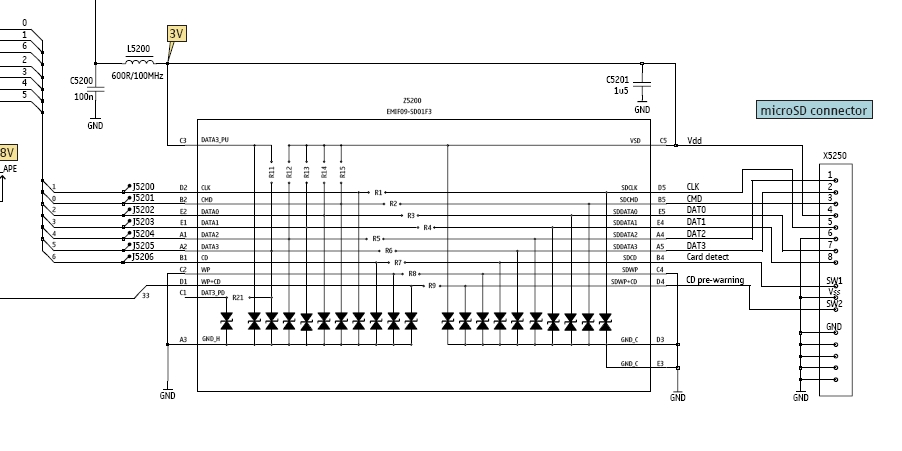
In this tutorial, the functioning of the memory card circuit in mobile phones will be explored. The previous post discussed the pin-outs and types of memory cards utilized in cellular devices. The accompanying block diagram illustrates how the removable...
Warning: include(partials/cookie-banner.php): Failed to open stream: Permission denied in /var/www/html/nextgr/view-circuit.php on line 713
Warning: include(): Failed opening 'partials/cookie-banner.php' for inclusion (include_path='.:/usr/share/php') in /var/www/html/nextgr/view-circuit.php on line 713