
25 w stereo power amplifier circuit
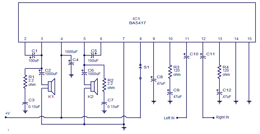
The BA5417 stereo amplifier IC is designed to deliver high-quality audio performance with minimal distortion, making it suitable for various applications, including low-power car audio systems. The circuit's configuration allows for efficient amplification with a straightforward setup, as it requires very few external components. The inclusion of decoupling capacitors ensures that the input signals are free from DC offsets, thereby maintaining audio fidelity.
In addition to the BA5417, other stereo amplifier circuits such as the BA5406 and TDA1554 are mentioned, each with its unique specifications. The BA5406 can also deliver 5 watts per channel into 4-ohm speakers, operating from a 12V DC supply. The TDA1554 is a popular design capable of outputting 22 watts per channel into 4-ohm loudspeakers, while the TDA2050 circuit can provide 32 watts per channel with a dual supply of ±18V DC. The TDA4935 features overload protection and thermal shutdown, delivering 15 watts into 4-ohm speakers at a 24V DC operating voltage. Lastly, the LM4780 audio amplifier IC can produce 120 watts with a dual supply of ±35V DC, incorporating features such as good power supply rejection and built-in mute circuitry. Each of these designs showcases various configurations and capabilities, catering to different audio amplification needs.BA5417 is a stereo amplifier IC with a lot of good features like thermal shut down, standby function, soft clipping, wide operating voltage range etc. The IC can deliver 5W per channel into 4 ohm loud speakers at 12V DC supply voltage. The BA5417 has excellent sound quality and low THD (total harmonic distortion) around 0. 1% at F=1kHz; Pout=0. 5W. Setup and working of this stereo power amplifier circuit is somewhat similar to the BA5406 based stereo amplifier circuit published previously. C10 and C11 are DC decoupling capacitors which block any DC level present in the input signals. C2 and C6 couples the amplifiers left and right power outputs to the corresponding loud speakers. C1 and C5 are bootstrap capacitors. Bootstrapping is a method in which a portion of the amplifiers is taken and applied to the input. The prime objective of bootstrapping is to improve the input impedance. Networks R1, C3 and R2, C7 are meant for improving the high frequency stability of the circuit. C4 is the power supply filter capacitor. S1 is the standby switch. C8 is a filter capacitor. R3 and R4 sets the gain of the left and right channels of the amplifier in conjunction with the 39K internal feedback resistors.
BA5406 stereo amplifier circuit: Simple stereo amplifier circuit that can deliver 5 watt per channel sound output into a 4 ohm speaker. Operates from 12V DC and requires very few external components. Suitable for low power car audio applications. TDA1554 stereo amplifier circuit: A very popular stereo amplifier design. This amplifier can output 22 watts per channel into 4 ohm loud speakers. This circuit can be also powered from 12V DC. Low distortion and noise. 2G—32 watts stereo amplifier circuit: High quality stereo amplifier design using TDA2050 IC. The circuit requires a /-18V DC dual supply. Power output is 32 watts per channel into 4 ohm speakers. Stereo amplifier based on TDA4935: A stereo amplifier design with a lot of great features like over load protection and thermal shut down.
The power out put is 2G—15 W into 4 ohm speakers. Operating voltage is 24V DC. Potentiometers for controlling the volume is also included in the circuit. 120W stereo amplifier circuit: A powerful stereo amplifier design using LM4780 audio amplifier IC from National Semiconductors. operates from a /-35V DC dual power supply. 2G—60 watt power output into 8 ohm loud speakers. The circuit has good power supply rejection and also there is a built in mute circuitry. 🔗 External reference
Related Circuits
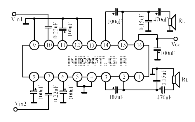
The D2025 is a dual audio power amplifier circuit designed as a stereo audio power amplifier integrated circuit. It comes in a DIP16 package and is applicable for various portable devices, such as tape recorders or portable stereo systems....
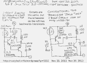
A schematic of a two-transistor Joule Thief was presented in a YouTube video by Sanjev21, which has since been removed. The two-transistor Joule Thief is a compact and efficient circuit designed to extract energy from low-voltage sources, such as depleted...
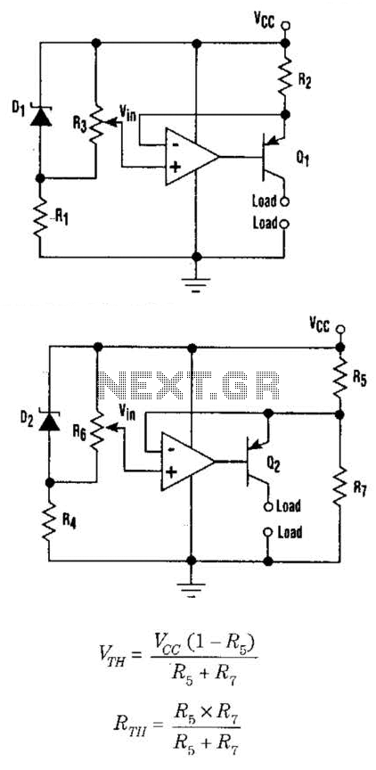
This setup can function as a cost-effective current source with an output accuracy of 1%. However, the voltage offset can activate the current source even when Vqq equals Vin. Modifying the configuration of Figure 1 can resolve the issue...
The input impedance of AC-coupled operational amplifier (op-amp) circuits is primarily determined by the resistance that establishes the DC operating point. When using CMOS op-amps, the input impedance is high, reaching up to 10 MΩ in current op-amps. For...
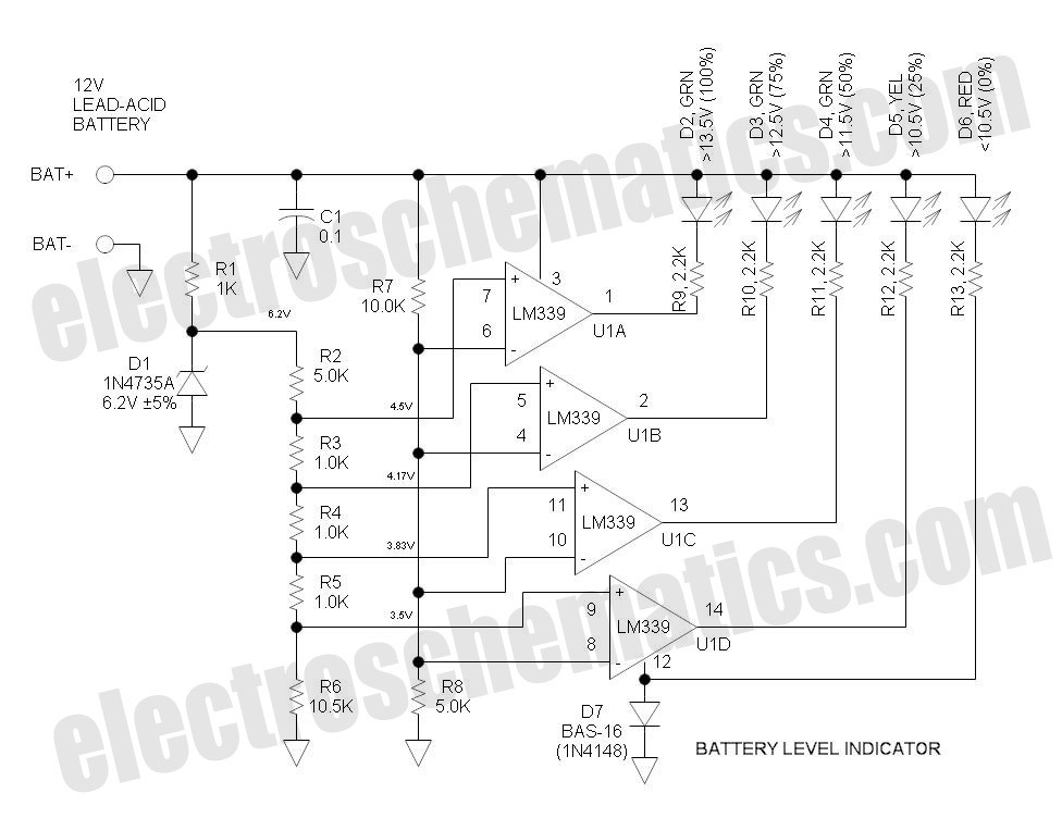
This battery level indicator features five LEDs that illuminate progressively as the voltage increases: Red indicates power connection (0%), Yellow signifies voltage greater than 10.5V (25%). The battery level indicator circuit utilizes a series of five light-emitting diodes (LEDs) to...
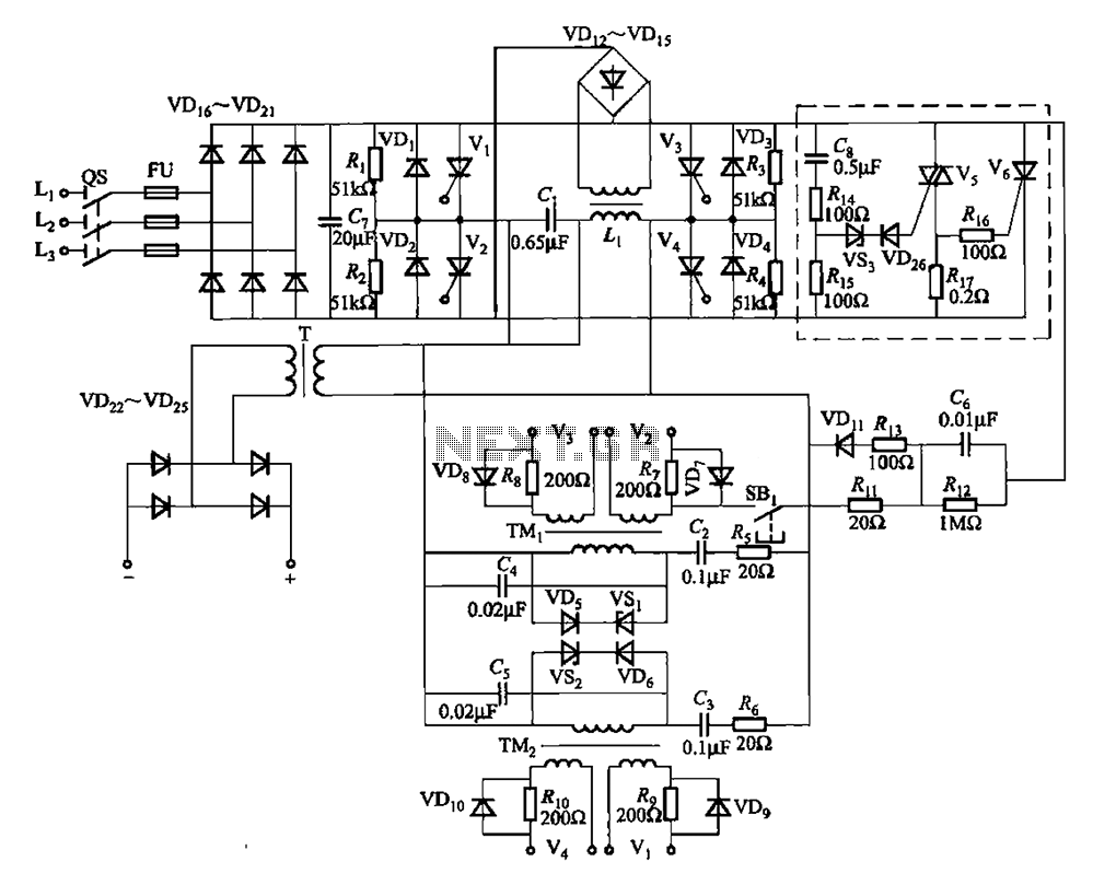
A 25kHz thyristor inverter welding machine circuit utilizes high-frequency operation to enable smaller transformer designs. The circuit diagram is illustrated in Figure 9-14. The no-load output voltage of the machine is 45V DC, with a peak voltage of 90V...