
Class-A audio Amplifier circuit
The frequency stabilization capacitor will need to be selected based on the closed loop gain - in some cases, it won't be needed at all (but unless you have decent test equipment to verify that the circuit is stable, leave it in). Be very careful if the load is capacitive (or worse, a resonant circuit, such as coaxial cable) - the circuit will almost certainly oscillate. If this happens, use a 100-ohm "stopper" resistor at the output - after the feedback return - otherwise, it will do no good at all.
Also, since the circuit is an opamp, it needs to have feedback resistors and a DC return path for the +ve input - just like any other opamp. Performance is very good with gains of up to 10 (perhaps more depending on what you want to use it for), and it can be made to have very wide bandwidth.
Suggested transistors (these are cheap, easy to get, and pretty good, too):
NPN - BC549 PNP - BC559 As always, use 1% metal film resistors for low noise and long-term stability.
However good this may look, it can be safely assured that it doesn't even come close to something like the NE5532 dual op-amp, and it draws a lot more current, too. However, it is an interesting circuit to fool about with and should actually give a good account of itself in traditional op-amp circuits.
One word of warning - the input impedance and bias current are much worse than even the poor old 741, but bandwidth, noise, and distortion can be expected to be much better. Just don't try to use it with really high impedance circuits, and don't expect the output to provide the +/- 20mA or so you are used to, because it won't. However, Project 37A is an excellent audio preamp that is based on the general ideas shown here, although the approach is different. In some cases, there are few choices - you end up having to use discrete and "outdated" circuitry because no available (or affordable) opamp has the required bandwidth.
This experimental circuit operates as a low current Class-A operational amplifier. The circuit's design emphasizes the use of a Class-A output stage, which inherently eliminates crossover distortion, a common issue in Class-AB amplifiers. The circuit features a high open-loop gain of 690,000, achieved with transistors that have a gain of 100. The Class-A output stage operates at a quiescent current of 11 mA, making it suitable for a range of supply voltages, typically from +/-12V to +/-20V, depending on the specifications of the selected transistors.
The differential input stage employs a long-tailed pair (LTP) configuration, which is critical in ensuring balanced collector currents for optimal performance. A key component in this configuration is the 2.7kΩ resistor placed between the base and emitter of transistor Q3, which may need adjustment based on the supply voltage and transistor characteristics to minimize DC offset. The incorporation of a multi-turn trimpot in this section allows for fine-tuning of the DC offset to achieve a target of 0V.
To ensure stability, a frequency stabilization capacitor may be necessary, particularly if the closed-loop gain is high. Caution should be exercised with capacitive loads, as they can induce oscillations within the circuit. In such scenarios, a 100Ω "stopper" resistor should be placed at the output to mitigate these effects.
The circuit requires feedback resistors and a DC return path for the non-inverting input, similar to standard op-amp configurations. Its performance is commendable, supporting gains up to 10, with the potential for even higher gains depending on specific applications. The choice of transistors, such as the BC549 for NPN and BC559 for PNP, is recommended due to their availability and performance characteristics. The use of 1% metal film resistors throughout the circuit is advisable to minimize noise and enhance long-term stability.
While this circuit presents an engaging platform for experimentation, it is important to note its limitations in comparison to more advanced op-amps like the NE5532. The input impedance and bias current are notably lower than that of classic op-amps such as the 741, although improvements in bandwidth, noise, and distortion may be realized. This circuit is not suitable for high-impedance applications and should be utilized with caution regarding output current capabilities, as it will not deliver the typical +/- 20mA output.The circuit presented is experimental, and should provide some fun to build and play about with. It has been built and tested, and works very well indeed. Please note that it is a low current Class-A opamp, and is incapable of driving low impedances. The minimum recommended load impedance is about 1k. It has the advantage of a Class-A output stage, so there is no possibility of crossover distortion, and in the version shown, (my simulator tells me that...) using transistors with a gain of 100, the final circuit has an open loop gain of 690,000. The Class-A output runs at a current of 11mA, and the circuit should work fine with supply voltages from +/-12 up to +/-20 or more (depending on the voltage rating of the transistors).
The circuit shown was both tested and simulated with +/-20V supplies, and different supply voltages (as well as variations in the transistor characteristics) will require that the value of the 2.7k resistor (between base and emitter of Q3) will need to be changed to minimise DC offset. This also ensures that the collector currents in the LTP are equal, maximising gain and minimising distortion.
A multi-turn trimpot can be used here to set DC offset to 0V. The frequency stabilisation capacitor will need to be selected based on the closed loop gain - in some cases it won't be needed at all (but unless you have decent test equipment to verify that the circuit is stable, leave it in). Be very careful if the load is capacitive (or worse, a resonant circuit, such as coaxial cable) - the circuit will almost certainly oscillate.
If this happens, use a 100 ohm "stopper" resistor at the output - after the feedback return - otherwise it will do no good at all. Also, since the circuit is an opamp, it needs to have feedback resistors and a DC return path for the +ve input - just like any other opamp.
Performance is very good with gains of up to 10 (perhaps more depending on what you want to use it for), and it can be made to have very wide bandwidth. Suggested transistors (these are cheap, easy to get, and pretty good, too): NPN - BC549 PNP - BC559 As always, use 1% metal film resistors for low noise and long term stability.
However good this may look, I can safely assure the reader that it doesn't even come close to something like the NE5532 dual op-amp, and it draws a lot more current, too. However, it is an interesting circuit to fool about with, and should actually give a good account of itself in traditional op-amp circuits.
One word of warning - the input impedance and bias current are much worse than even the poor old 741, but bandwidth, noise and distortion can be expected to be much better. Just don't try to use it with really high impedance circuits, and don't expect the output to provide the +/- 20mA or so you are used to, because it won't.
However, Project 37A is an excellent audio preamp that is based on the general ideas shown here, although the approach is different. In some cases, there are few choices - you end up having to use discrete and "outdated" circuitry, because no available (or affordable) opamp has the required bandwidth.
🔗 External reference
Related Circuits
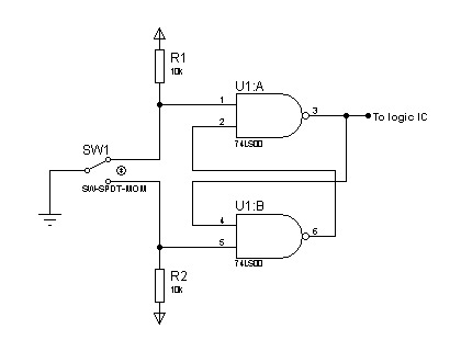
In most digital electronics projects that utilize various types of switches, switch bounces are frequently encountered. These are additional glitches that occur following the actual operation of the switch. These small pulses can disrupt the proper functioning of the...
This process can be simplified by utilizing a display kit from PJRC, which includes the appropriate firmware installed on the display, a functioning pushbutton board, and the necessary cables. The PJRC display features a 4-pin connector compatible with the...
The amplifier is based on an integrated circuit TDA2822M. With this circuit, an amplifier can be built with up to 2 W. This much power circuit is able to supply only at peak times; continuous excitation would not be...
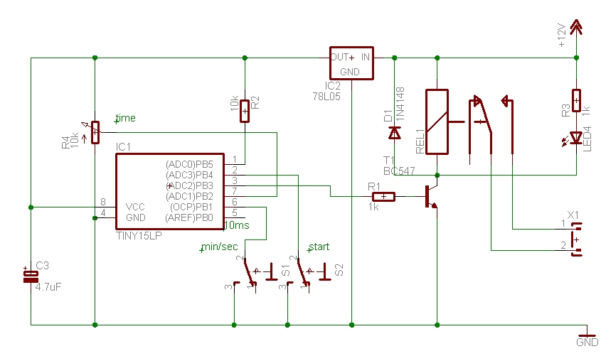
The time can be set using a potentiometer ranging from 1 minute to 1023 minutes, approximately 17 hours. A pushbutton initiates the timing process, activates a relay, and the timer will deactivate the relay once the set time has...
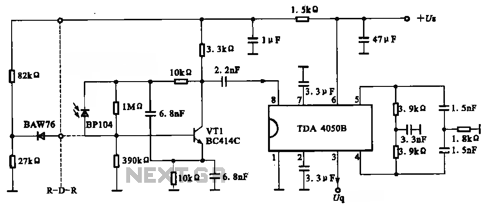
The circuit depicted is an infrared receiver circuit. It primarily consists of an infrared remote control signal switching circuit, designated as VRI, along with signal amplification, filtering, and rectifying integrated circuits, specifically the TDA4050B. The BP104 component serves as...
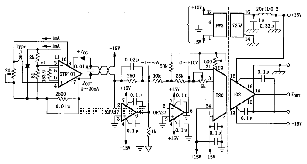
The circuit depicted in the figure features the ISO102 and XTR101 components, forming an isolated remote transmitter circuit equipped with isolated thermocouple cold-junction compensation. The circuit comprises four main parts: the current loop amplifier XTR101, the isolation amplifier ISO102,...