
Cat toys electronic circuit

The described circuit utilizes a piezoelectric ceramic sensor to capture acoustic signals, specifically the sound of clapping. The piezoelectric effect allows the sensor to convert mechanical stress from the sound waves into an electrical voltage, which is then processed by the circuit. The initial electrical signal generated by the piezoelectric sensor is often weak; therefore, it is amplified using transistor VT1. This amplification is crucial for ensuring that the subsequent components receive a sufficiently strong signal for further processing.
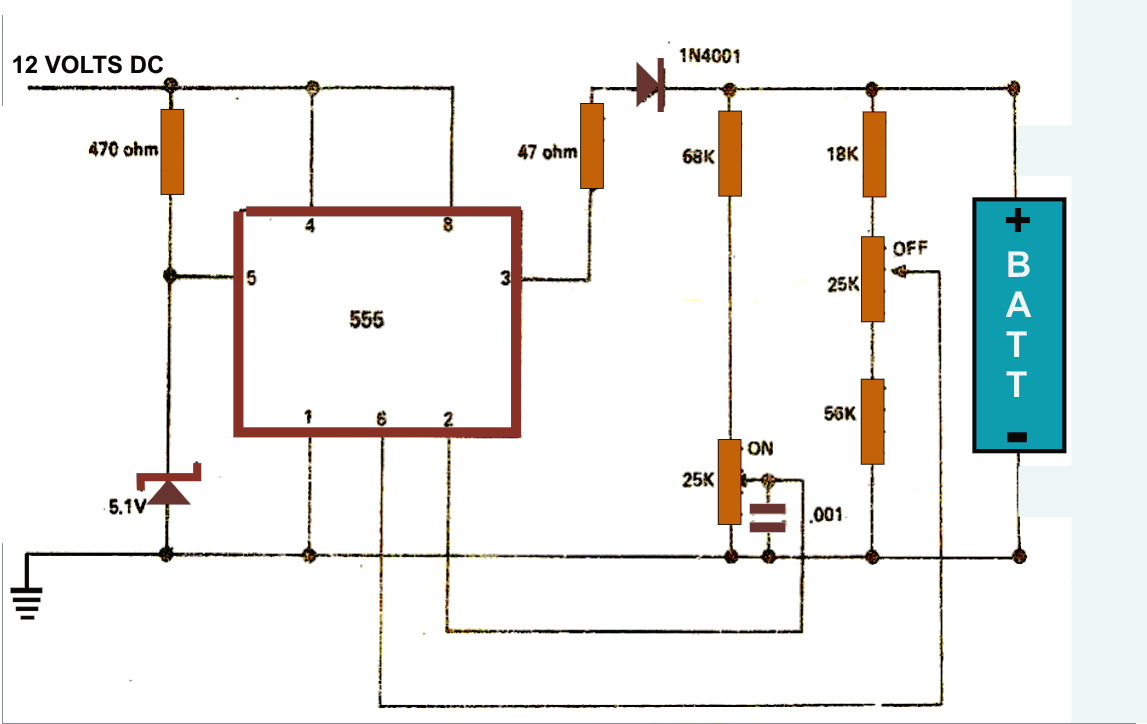
The amplified signal is coupled to the base of a 555 timer IC through coupling capacitor C1. The 555 timer is configured in a monostable or astable mode, depending on the intended application. In this case, the configuration appears to be set to generate a pulse output when triggered by the clapping sound. Pins 2 and 3 of the 555 timer are key in determining the timing characteristics of the output signal, which can be adjusted using external resistors and capacitors.
The output from the 555 timer is then used to drive a pair of transistors, VT2 and VT3, which are configured to form an oscillator circuit. This oscillator is responsible for generating the frequency needed to drive a speaker. The output from the oscillator circuit is connected to a speaker, designated as B, which produces a meowing sound in response to the initial clapping sound detected by the piezoelectric sensor. The overall design of this circuit enables the transformation of an acoustic signal into an audible sound, demonstrating the interplay between sound detection, signal amplification, and sound reproduction within electronic circuits.Circuit works: When you clapping sound through the piezoelectric ceramic HTD people seized converted into an electrical signal fed to the transistor VT1 after amplification, through the coupling capacitor C1 to the base of the electrical path 555 2 feet, 3 feet high output power of 555 level. In this case the VT2, VT3, T, B, called oscillator consisting of cats began to give power to make T, speaker B issued meow sound.
Related Circuits
The simple battery charger circuit design presented here utilizes the versatile IC 555 as its primary component. This circuit is capable of charging various types of rechargeable batteries within the specified limits outlined in the article. The battery charger circuit...
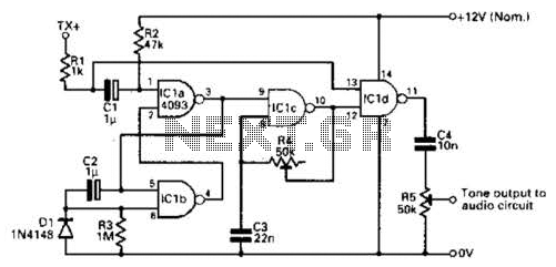
The RF oscillator utilizes inverter N2 and a 10.7 MHz ceramic filter to drive the parallel combination of inverters N4 to N6 through inverter N3. Since these inverters are connected in parallel, the output impedance is low, allowing direct...
The PCA84C-440/441 is a single-chip microcomputer integrated circuit produced by Philips. It is widely utilized in both domestic and imported large screen color televisions, including those manufactured by Philips and other brands. The PCA84C-440/441 IC is housed in a...
Half of a Motorola MG14538B dual precision retriggerable monostable multivibrator is utilized to create an extended on-time timer circuit. This type of circuit can function as a switch debouncer. Such circuits are commonly implemented in digital applications, where every...
The mixer features two stereo phono inputs and two stereo line-level inputs, along with one stereo bonded channel. It also includes a microphone input and a stereo output with adjustable gain. The mixer is designed to accommodate a variety of...

This is a simple LED blinker or flasher designed for decorative purposes. The circuit features 20 high-brightness LEDs that flash alternately, creating a vibrant color display. The LED blinker circuit typically consists of several key components including a microcontroller or...