
CD4093 Water Level Sensor (Detector)
The water level sensor circuit employs a NAND logic gate to create a square wave oscillation, which is essential for detecting varying water levels. The circuit typically consists of a few key components: a NAND gate, resistors, capacitors, and conductive probes that serve as the sensing elements.
When water is present, it acts as a conductive medium, allowing current to flow through the probes. The resistance between the probes changes depending on whether they are submerged in water or exposed to air. This change in resistance alters the oscillation frequency generated by the NAND gate.
The output from the NAND gate can be connected to additional components such as an LED indicator or a relay. The LED will illuminate when the water level reaches a certain threshold, providing a visual indication of the water level. In contrast, the relay can be used to control a pump or valve, enabling automatic filling or draining of a tank based on the detected water level.
To ensure reliable operation, the circuit may incorporate a filtering capacitor to smooth out any noise in the signal and provide stable oscillation. Additionally, the choice of resistor values can be adjusted to calibrate the sensitivity of the water level detection, allowing for customization based on specific application requirements.
Overall, this water level sensor circuit is a simple yet effective solution for monitoring water levels in various applications, including aquariums, water tanks, and industrial processes.This water level sensor (detector) circuit uses a standard NAND logic gate to produce oscillation and to detect the water level. Oscillation is included inside.. 🔗 External reference
Related Circuits
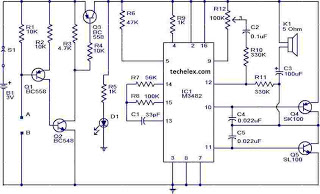
This is a simple alarm circuit that produces a musical tone when water or any conductive liquid comes into contact with the two sensor wires provided. The circuit utilizes four transistors and one melody generator IC (M3482). When water...
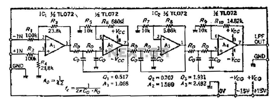
A 36 dB/octave Butterworth filter consists of three sub-structures, each stage containing two filter sections. The design aims to achieve specific 3 dB frequency characteristics. The filter needs to be normalized to a value of 0 across all levels,...
This schematic diagram illustrates a TMP01 Fahrenheit scale temperature sensor circuit. The circuit is designed to convert VPTAT into an output that can be easily read. The TMP01 is a precision temperature sensor that provides an analog voltage output proportional...
The integrated circuit input side contains an oscillating circuit, where the oscillation frequency is determined by the external components L1, C1, and the sensor's equivalent capacitance. The equivalent capacitance increases as the sensor is immersed in liquid. The oscillating...
The following circuit illustrates an Ultrasonic Sensor Circuit Diagram. This circuit is based on the MAX232 IC. Features include a quiescent current of 150mA. The Ultrasonic Sensor Circuit utilizes the MAX232 integrated circuit, which is primarily designed for converting signals...
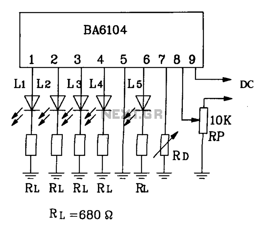
BA6104 is a five-digit LED level meter driver integrated circuit (IC) that features a basic application circuit. The input stage employs a PNP transistor with a composite base input, resulting in high input impedance. The output stage is configured...
Warning: include(partials/cookie-banner.php): Failed to open stream: Permission denied in /var/www/html/nextgr/view-circuit.php on line 713
Warning: include(): Failed opening 'partials/cookie-banner.php' for inclusion (include_path='.:/usr/share/php') in /var/www/html/nextgr/view-circuit.php on line 713