
Using the same parameters more convenient level 36dB-oct low-pass filter design
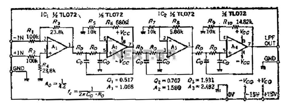
A 36 dB/octave Butterworth filter is designed to provide a smooth frequency response with minimal ripple in the passband. The filter is structured in three stages, each containing two filter sections, which allows for a gradual roll-off and enhances the overall performance of the filter. The specific frequency characteristics are critical, as they define the filter's cutoff frequency and the transition between the passband and the stopband.
Normalization of the filter response to a value of 0 is essential for maintaining consistent gain across all levels. This normalization process involves adjusting the gain settings for various operational amplifiers (A1 to A4) used within the circuit. The selected values of 0.517, 0.707, and 1.931 at port 1 indicate specific gain adjustments that must be made to achieve the desired output characteristics.
The operational amplifiers play a vital role in the feedback mechanism of the filter. The gain of each operational amplifier is influenced by the feedback resistors, which can be calculated using the provided formula. This calculation is crucial for ensuring that the filter operates within its intended parameters, allowing for effective signal processing without distortion.
The passband gain of 4.2 times indicates that the output signal will be amplified relative to the input signal. Consequently, the input amplifier A1 must be configured to have an attenuation of 1/4.2 to ensure that the overall gain remains balanced. Proper management of the series input is critical to prevent saturation, which can introduce high-frequency harmonics that the filter may not adequately suppress.
In designing the circuit, careful consideration must be given to component selection and layout to minimize interference and maintain signal integrity. The performance of the Butterworth filter is heavily reliant on the precision of the components used, as well as the accuracy of the calculated resistor values. By adhering to these design principles, the filter can achieve its intended function of providing a clean and stable output signal across the specified frequency range.36dB/ocf Butterworth filter consists of three sub-ruined structure, each stage box with two filter sections c work zdB/ocf), in order to point a 3dB frequency characteristics n ormalized to a value of 0 at all levels must be adjusted separately 0. 517,0.707,1.931 have to use port 1 when the gain of the amplifier to increase the value of the way the mouth, according to a, 3 ten thousand bamboo-level number, l, 2,3), and calculate the required gain.. OP amplifier Ai ~ A4 increase the feedback gain determined by the resistor, 4- determined after. R, can be calculated; R. ( .- 1) 10 10l, the calculation result as the circuit diagram parameters. It should be noted that: passband gain of 42, Azx As, namely the total gain of 4,2 times, the input amplifier A.
Attenuating circuit should be 1/4.2, so that A 1. If not cope Series, input increases, the background had a lot of saturated filter high harmonics filters can not filter out the complete barrier.
Related Circuits
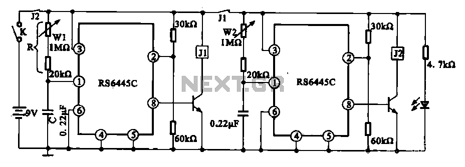
The timing integrated circuit (IC) RS6445C functions as a blocking oscillator. It features two segments, WI and W2, which are utilized to adjust the working time and the closure time. These adjustments can be continuously set within a range...
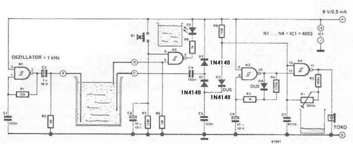
The circuit diagram is straightforward and operates as follows: the N1 Schmitt trigger functions as an oscillator, producing a frequency of approximately 1 kHz. When there is sufficient water in the tank, alternating voltage flows from electrode A to...
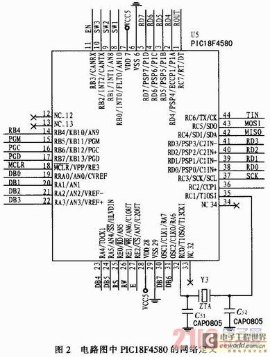
The grain measurement system evaluates the primary technical indicators of grain quality, including the miscellaneous rate and volume density. This measurement not only determines the grade and price of the grain but also directly influences its processing quality and...
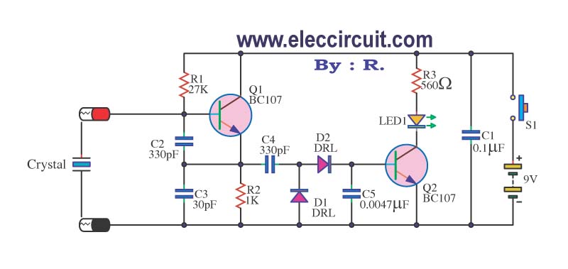
A multimeter cannot be used to test a crystal oscillator. Instead, a dedicated circuit is required, capable of checking crystals within the frequency range of 100 kHz to 900 MHz. This circuit is easy to construct and cost-effective. To construct...
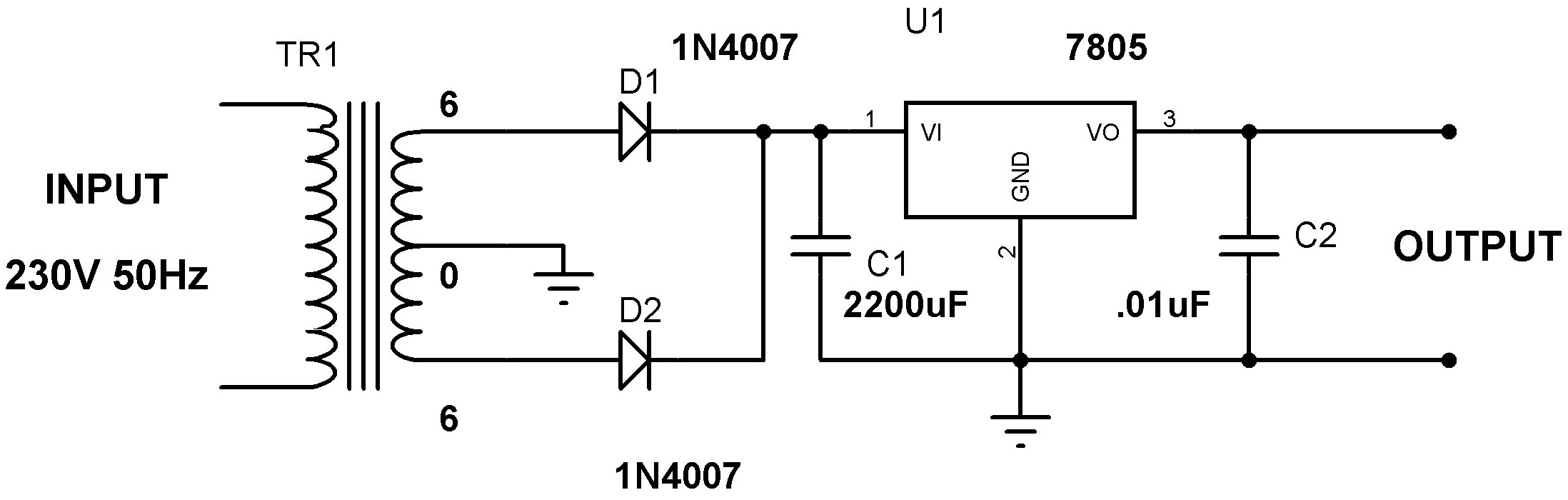
Designing a power supply requires careful consideration of each component. This discussion will focus on the design of a regulated 5V power supply. Note: Any transformer that provides a secondary peak voltage of up to 35V can be used;...

FAN7710 Ballast Control circuit design for Compact Fluorescent Lamps electronic project. The FAN7710 is a specialized integrated circuit designed for the control of ballast systems in compact fluorescent lamps (CFLs). This circuit typically operates in a high-frequency range, facilitating efficient...
Warning: include(partials/cookie-banner.php): Failed to open stream: Permission denied in /var/www/html/nextgr/view-circuit.php on line 713
Warning: include(): Failed opening 'partials/cookie-banner.php' for inclusion (include_path='.:/usr/share/php') in /var/www/html/nextgr/view-circuit.php on line 713