
cdmp3 cd with cdroom circuit diagram
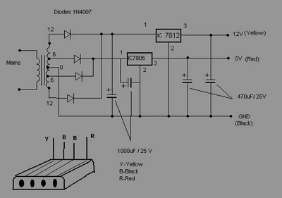
The described circuit serves as a power supply for a CD-ROM drive, facilitating its use as an independent audio playback device. The power supply must deliver two voltage levels: +5V and +12V, which are standard for powering CD-ROM drives. The +5V supply typically powers the digital logic circuits within the CD-ROM, while the +12V supply is necessary for the motor that spins the disc and for other mechanical components.
To construct this circuit, a transformer or a switching power supply can be utilized to convert the mains voltage to the required output levels. A bridge rectifier can be employed to convert the AC voltage from the transformer to DC voltage, followed by filtering capacitors to smooth the output. Voltage regulators may be used to ensure stable output voltages at +5V and +12V.
The D-type power connector will be essential for interfacing the power supply with the CD-ROM drive. The pin configuration should be checked against the specifications of the CD-ROM to ensure proper connection. Additionally, implementing protection features such as fuses or thermal cutoffs can enhance the reliability and safety of the circuit.
Overall, this setup allows for a versatile audio solution, enabling users to enjoy CD audio without the need for a computer, making it suitable for various applications, including portable audio systems or integration into custom audio projects.Most of the CDROMS available have an Audio-Out Output to either plug in the headphones or connect it to an amplifier. This circuit enables one to use the CDROM as a stand alone Audio CD player without the computer. This circuit is nothing but a power supply which supplies +5v, +12V and Ground to the CDROM drive and hence can be used without the co
mputer. You should buy a D-type power connecter to connect this circuit`s outputs to the CDROM. 🔗 External reference
Related Circuits
An FM transmitter circuit that utilizes a low power configuration, employing an operational amplifier as an audio preamplifier and a single transistor to function as the RF amplifier. This FM transmitter circuit is designed for low power applications, making...
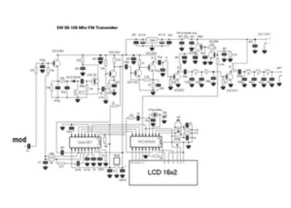
This is a straightforward high-quality PLL FM transmitter with a typical output power of 5 W and a no-tune design. It features RDS/SCA input and audio/MPX input with optional pre-emphasis and can operate with or without a stereo encoder....
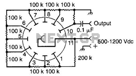
This circuit is representative of the typical application of a photomultiplier tube. The circuit depicted is AC coupled; however, if DC coupling is required, the capacitor can be removed, and an appropriate interfacing method should be employed. A common...
IR appliances use pulses (control signals) sent over a modulated IR carrier wave. The carrier wave may be modulated at various frequencies, 36-38KHz being the most popular. Some Satellite receivers use even higher frequencies than this. The IR1 remote...
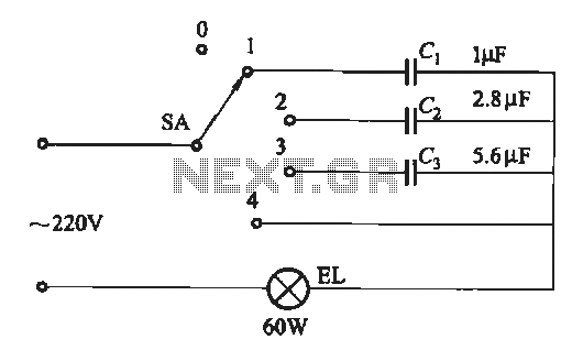
A dimming circuit capacitor circuit is illustrated in Figure 2-63. When the switch SA is moved from position "1" to "3," the capacitance increases in ascending order, resulting in the light bulb brightness also increasing correspondingly. When SA is...
A 1997 Dodge Dakota extended cab sport owner is seeking a wiring diagram for the tail light or brake light system. To locate the wiring diagrams for the tail light and brake light systems of a 1997 Dodge Dakota extended...