
FM Transmitter Circuit
This FM transmitter circuit is designed for low power applications, making it suitable for personal use or small-scale broadcasting. The circuit diagram consists of several key components that work together to generate and amplify an FM signal.
The operational amplifier (op-amp) serves as the audio preamplifier, which processes the audio input signal. This preamplifier stage is crucial for boosting the weak audio signals to a level suitable for further amplification. The op-amp is typically configured in a non-inverting mode to maintain signal integrity while providing the necessary gain.
Following the audio preamplifier, the RF amplifier stage is implemented using a single transistor. This transistor is responsible for modulating the audio signal onto a radio frequency carrier wave, effectively creating the FM signal that can be transmitted over the air. The choice of transistor is critical, as it must be capable of handling the frequency range of interest and providing sufficient gain to ensure a clear transmission.
The circuit also includes a series of resistors that establish the biasing conditions for the op-amp and the transistor. The values of these resistors, such as R1 (4.7 kΩ), R2 (4.7 kΩ), R3 (4.7 kΩ), R4 (150 kΩ), R5 (220 Ω), R6 (4.7 kΩ), R7 (3.9 kΩ), and R8 (120 Ω or 82 Ω), are selected to optimize performance, ensuring that the op-amp operates within its linear range and that the transistor is properly biased for efficient amplification.
The circuit may also include capacitors for coupling and decoupling purposes, which help to filter out unwanted noise and stabilize the power supply. Additionally, an inductor may be used in conjunction with the transistor to form a tank circuit, allowing for fine-tuning of the transmission frequency.
Overall, this low power FM transmitter circuit is a practical and efficient design for those looking to explore the fundamentals of radio frequency transmission and audio amplification. Proper assembly and testing of the circuit components will yield a functional transmitter capable of broadcasting audio signals wirelessly.FM Transmitter Circuit An low power FM Transmitter using an op-amp as the audio preamp and a single transistor as the RF amplifier. Circuit Diagram Parts List R1 4K7 R4 150K R7 3K9 (2K7)R2 4K7 R5 220R R8 120R (82R)R3 4K7 R6 4K7A.. 🔗 External reference
Related Circuits
This is a police tone circuit for a siren. It is simple and easy to construct. VR1 and VR2 are used to adjust the delay of the siren sound. The design is straightforward and uncomplicated. The police tone siren circuit...
The pulse telephone 160 168 controller circuit is depicted above. This controller can be installed either on the telephone or on the switchboard of the trunk line. It effectively prevents unauthorized dialing of numbers 160 and 168. Diodes D1...
This complete high quality, low noise 5-BAND GRAPHIC EQUALIZER circuit is based around Monolithic Linear integrated circuit LA3600 manufactured by SANYO. This circuit is very easy to build and has good Quality. You can use it with Portable component...
Nokia BL-4C and BL-5C are 3.7V, 700-1000mAh (various) lithium-ion batteries that have three terminals. These terminals include a positive terminal, a ground, and a BSI (Battery Status Indicator) terminal, which presents a fixed resistance value that needs to be...
Operating radio transmitters without a license is illegal in most countries, so caution is advised with transmitter circuits. This FM low-power circuit is designed to operate within the 87-108 MHz band II, providing a range of approximately 20 to...
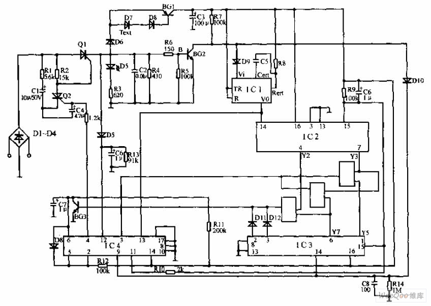
The electronic fishing shrimp machine circuit consists of an astable oscillator, an inverter circuit, and a high-voltage output circuit, as depicted in Figure 20. The astable oscillator circuit includes a time-base integrated circuit (IC), resistors R3 and R4, a...
Warning: include(partials/cookie-banner.php): Failed to open stream: Permission denied in /var/www/html/nextgr/view-circuit.php on line 713
Warning: include(): Failed opening 'partials/cookie-banner.php' for inclusion (include_path='.:/usr/share/php') in /var/www/html/nextgr/view-circuit.php on line 713