
ceiling fan regulator motor speed
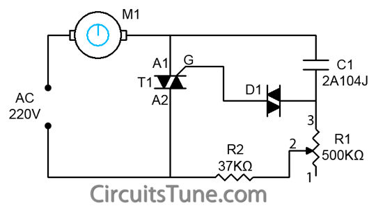
The ceiling fan regulator circuit utilizes a TRIAC (Z0607) as the main switching element, allowing for the control of the AC voltage applied to the fan motor. The TRIAC operates by changing its state from off to on when a gate signal is applied, effectively controlling the power delivered to the motor. The variable resistor R1, with a resistance of 500K ohms, allows for the adjustment of the phase angle of the AC waveform, which in turn modifies the average voltage reaching the fan motor, thus controlling its speed.
The capacitor C1 (2A104J), a polyester film capacitor, plays a crucial role in the circuit by providing phase shift and stabilizing the TRIAC operation. The capacitor is charged and discharged in conjunction with the TRIAC's gate control, enabling the precise timing needed for effective speed regulation.
The overall design of the circuit is straightforward, making it suitable for hobbyists and professionals alike. The simplicity of the circuit allows for easy assembly and troubleshooting, with minimal components required. Proper heat dissipation measures should be considered for the TRIAC, as it may generate heat during operation, especially at higher speeds.
This ceiling fan regulator circuit is ideal for applications requiring variable speed control in ceiling fans, ensuring energy efficiency and improved comfort in residential or commercial settings.This is a simple ceiling fan regulator circuit diagram. It is used to control the speed of a ceiling fan. In the other words it is an AC motor speed controller circuit, as because its control the speed of a AC motor(Ceiling Fan). This ceiling fan regulator circuit built with few numbers of parts. The circuit mainly based on Z0607 TRIAC. This is a low power AC semiconductor device. Generally which is used to controlling speed of low power ac motor speed. In this ceiling fan regulator circuit, R1=500K is a variable resistor that is used to adjust the fan speed. Capacitor C1 2A104J is a Polyester film capacitor. 🔗 External reference
Related Circuits
A DC motor reversing circuit using non-latching push button switches. Relays control forward, stop, and reverse action, and the motor cannot be switched from forward to reverse unless the stop switch is pressed first. The described circuit employs a system...
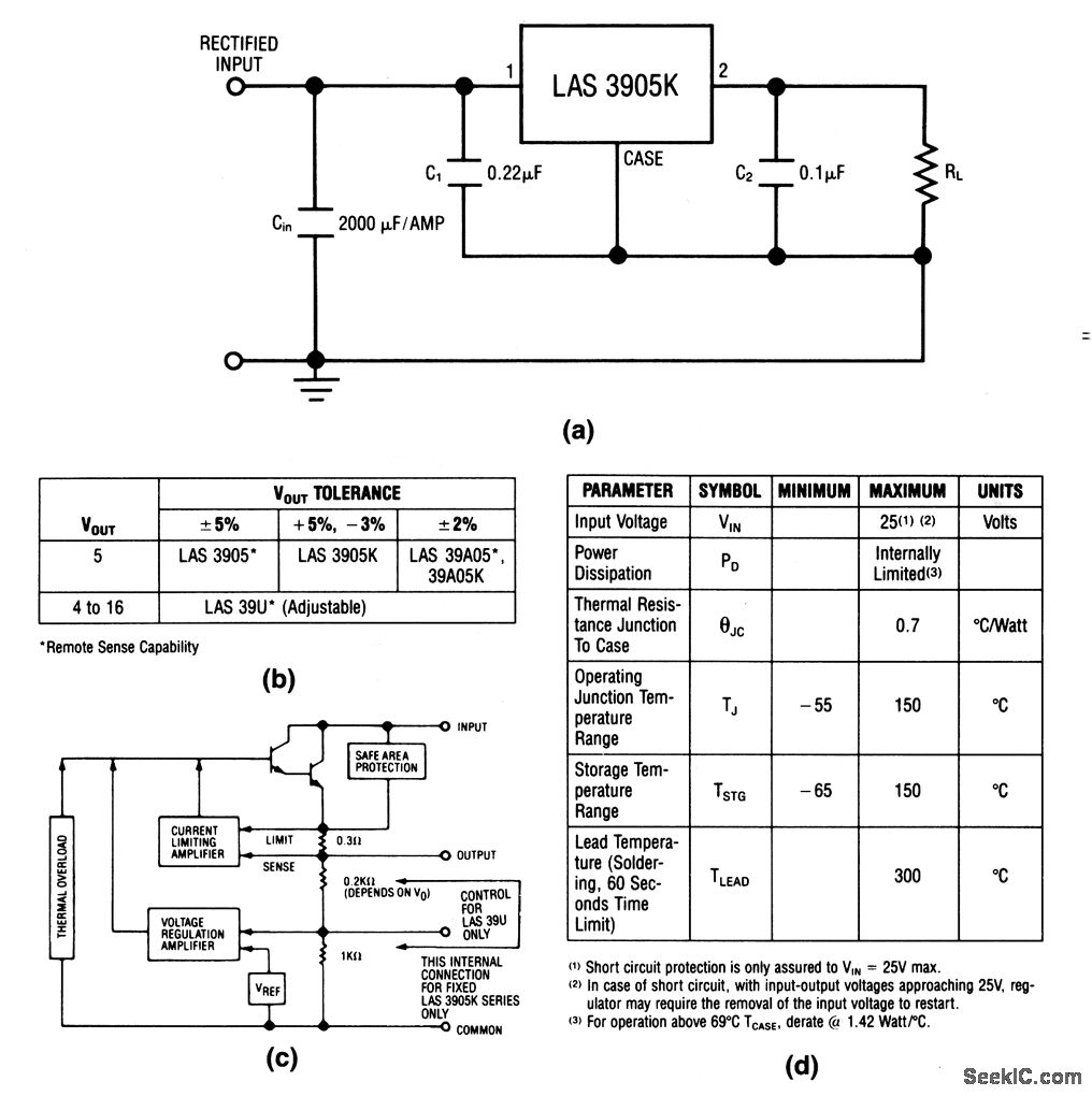
The LAS3905 series voltage regulators are integrated circuits (ICs) that incorporate all components required for linear voltage regulation, including safe-area protection, thermal overload protection, and current limiting. The output voltage and tolerance for the various LAS3905 part numbers are...
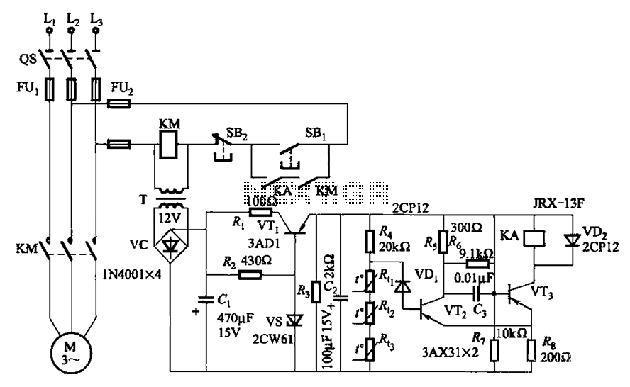
A P-type transistor (VT2, VT3) and other components form a common emitter-coupled trigger, functioning as a Schmitt trigger device. This setup serves as a switching circuit to detect changes in the resistance of a PTC thermistor, thereby controlling the...
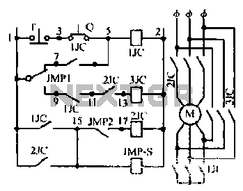
Motor windings are set to connect in a Y configuration while the load is active. The system includes an electric suction mechanism, and the motor is designed to operate under specific conditions. It is rated for 600 revolutions per...
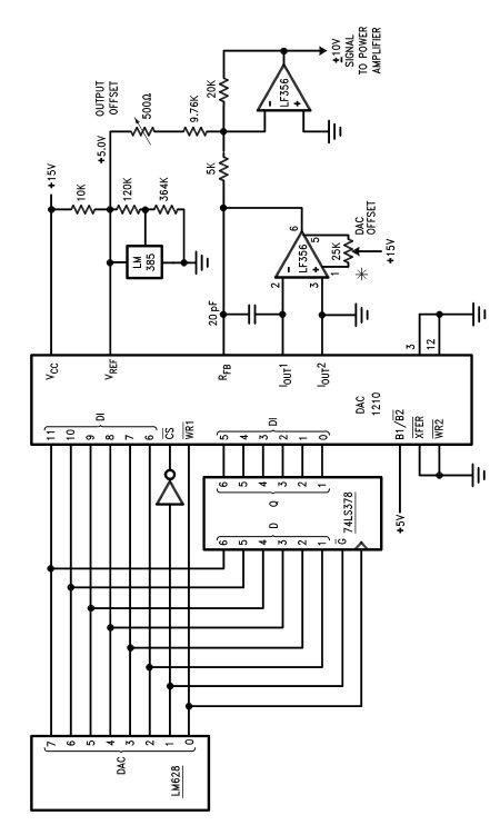
The LM628 and LM629 dedicated motion-control processors can be utilized to design various applications involving DC and brushless DC servo motors, as well as other servomechanisms. The power path of this electronic project, which functions as a motor driver,...
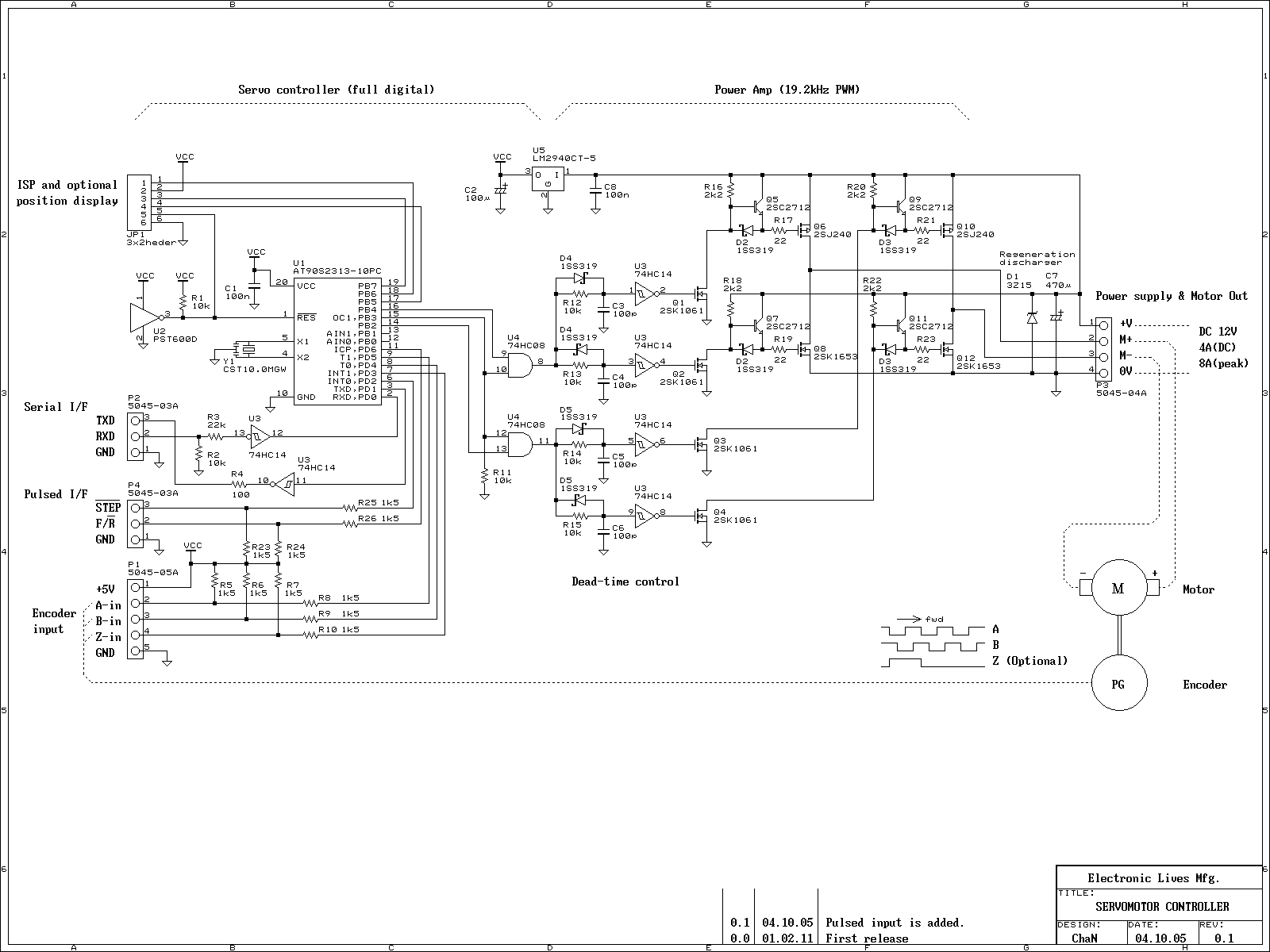
This is an experiment on the closed loop DC servomotor control system (SMC). It will be able to be used for practical use with/without some modifications. The closed loop servo mechanism requires real-time servo operations, such as position control,...
Warning: include(partials/cookie-banner.php): Failed to open stream: Permission denied in /var/www/html/nextgr/view-circuit.php on line 713
Warning: include(): Failed opening 'partials/cookie-banner.php' for inclusion (include_path='.:/usr/share/php') in /var/www/html/nextgr/view-circuit.php on line 713