
Cell Phone Charger Using 1.5V Battery
This cell phone charger circuit is designed to provide a reliable charging solution using a 1.5V battery as the power source. The circuit typically consists of several key components, including a voltage regulator, a charging controller, and a connection interface for the phone.
The core of the circuit is the voltage regulator, which steps up the voltage from the 1.5V battery to the required charging voltage for the phone, usually around 5V. Commonly used voltage regulators for this purpose include the LM7805 or a boost converter circuit that can efficiently increase the voltage while maintaining a stable output.
A charging controller is essential to manage the charging process, ensuring that the phone battery is charged safely and efficiently. This component monitors the voltage and current flowing into the phone, preventing overcharging, which can damage the phone's battery. The TP4056 is a popular choice for lithium-ion battery charging applications, providing integrated protection features.
The connection interface typically includes a USB output, allowing standard USB cables to be used for charging various phone models. Proper connectors and wiring should be employed to ensure a secure and reliable connection between the charger circuit and the phone.
In addition to the primary components, it is advisable to include capacitors for smoothing the output voltage and filtering any noise that may affect charging performance. A diode may also be included to prevent reverse current flow, protecting the battery and the circuit from potential damage.
Overall, this cell phone charger circuit provides an effective solution for charging mobile devices in situations where conventional mains power is unavailable, making it a valuable tool for emergency situations or outdoor activities.Use this cell phone charger circuit and a 1.5V battery when you do not have main power and need to charge your phone 🔗 External reference
Related Circuits
A simple pulse modulator circuit can be constructed using a 555 integrated circuit (IC). The 555 chip features a special modulator input located at pin 5. Below is the schematic diagram of the circuit. The pulse modulator circuit utilizing the...
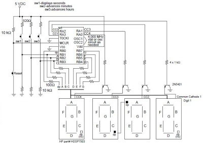
A digital clock project utilizing the PIC16C54 microcontroller can be constructed using the provided circuit diagram. This electronic project features a straightforward time-of-day clock that includes four seven-segment LED displays and three input switches, along with an additional reset...
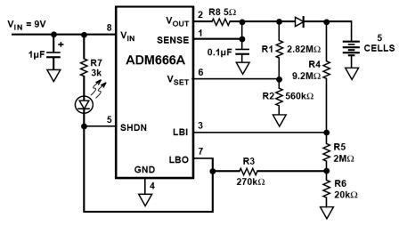
NiMH charger circuit diagram using ADM66A. Related searches include charger circuit, NiMH charger circuit, lead acid battery charger circuit, LiPo charger circuit, automatic battery charger circuit, simple battery charger circuit, lithium battery charger circuit, charger circuit diagram, and 12V...
This circuit allows for the construction of a compact tracking transmitter that can be detected using an FM broadcast band radio receiver. The transmitter operates on a power source of any 1.5V battery or power supply. It has a...

A cost-effective nickel-cadmium battery charger using the LM393, featuring the following characteristics: (1) It provides constant current charging interspersed with high current discharge. The charging current is approximately 300mA, while the discharge current increases with battery voltage, reaching nearly...
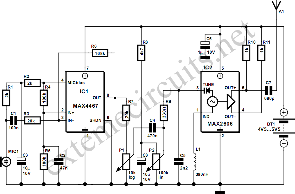
This project involves a simple and cost-effective transmitter that allows for speech transmission over a short range, functioning effectively as a cordless microphone. The circuit utilizes two integrated circuits from Maxim. The first, IC1, is the MAX4467, which amplifies...