
digital clock using with pic16c54
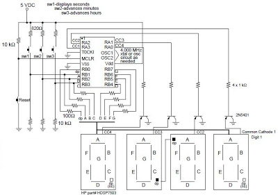
The digital clock design based on the PIC16C54 microcontroller operates as a real-time clock, effectively managing time display and user interaction. The circuit utilizes four seven-segment displays to present hours, minutes, and seconds in a clear format. The architecture relies on a microcontroller to control the logic and timing functions, with PORTA designated for controlling the common cathode of the displays. By employing transistors, the circuit ensures that the microcontroller does not exceed its current limits, thus enhancing reliability and longevity.
The input switches play a crucial role in user interaction. SW1 is dedicated to displaying seconds, allowing the user to monitor the passing seconds in real-time. SW2 and SW3 facilitate the setting of minutes and hours, respectively, providing a user-friendly interface for time adjustments. The reset switch, while not typically part of the final design, offers an additional layer of functionality for reinitializing the clock.
To ensure optimal brightness of the LED segments, 100-ohm resistors are used in series. This component selection is critical, as it balances the current flowing through the LEDs, preventing burn-out while maintaining visibility. Adjustments to the resistor values may be necessary depending on the specifications of different seven-segment displays that may be used in the project.
Overall, this digital clock project exemplifies the integration of microcontroller technology with basic electronic components to create an effective timekeeping device. The design principles and circuit layout can serve as a foundation for further developments or enhancements in digital clock applications.Digital clock project based on the PIC16C54 microcontroller can be designed using the following circuit diagram. This digital clock electronic project based on the PIC16C54 is a simple time-of-day clock incorporating four seven-segment LED displays and three input switches.
There is also an additional reset switch that would not normally be incor porated into the final design. The common cathode for each display is turned on with transistors connected to the four I/O lines of PORTA. A low output turns on the PNP transistor for the selected display. The PORTB pins activate the LED segments. Pressing SW1 will cause seconds to be displayed. The time is set by pressing SW2 to advance minutes, and SW3 to advance hours. The displays used were common cathode and turned on with transistors to avoid trying to sink too much current into the PIC16C5X.
100 W resistors were used in series with the segments to obtain the desired brightness. Different values may be required if different displays are used. This digital clock project based on the PIC16C54 microcontroller ( circuit and software ) was designed by Dan Matthews Microchip Technology Inc. Download Source Code 🔗 External reference
Related Circuits
The input mentions the 89S51/52 microcontrollers, but the accompanying image shows the 89C51. Clarification is needed regarding which microcontroller should be used with the provided .hex file without requiring changes to the file. The 89S51 and 89S52 are part of...
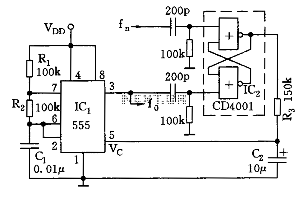
The circuit illustrated consists of a 555 timer along with resistors R1 and R2, and capacitor C1, forming a composition-controlled multivibrator. The oscillation frequency is influenced not only by the RC time constant but also by the adjustment of...
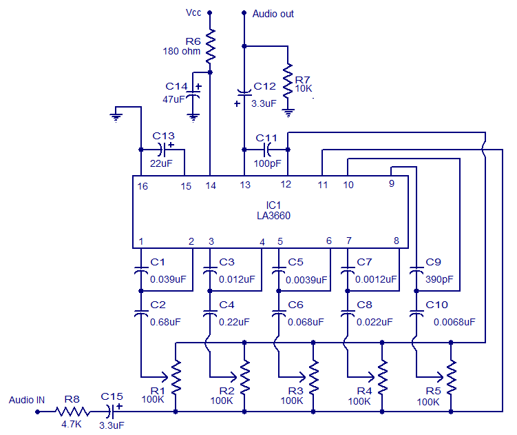
The graphic equalizer described is based on the LA3600 integrated circuit from Sanyo Semiconductors. The LA3600 is a single operational amplifier, 5-band graphic equalizer IC that is well-suited for applications such as portable stereo systems, radios, home theater systems,...
To explain in a little more detail, using the ATMEGA8's internal 2.5 volt band gap reference means that by using a resistive divider ahead of the A-to-D converter, the input could be scaled such that any voltage range from...
Measurement of physiological parameters such as heart rate and respiration rate is essential in the medical field. A simple method for measuring respiration rate utilizes a displacement transducer, which is fast and cost-effective. This method allows for the measurement...
For hobbyists or professional electronic engineers engaged in various electronic experiments, troubleshooting, or testing, it is essential to provide a wide range of variable options. In electronic engineering, the ability to manipulate and measure a wide range of variables is...