
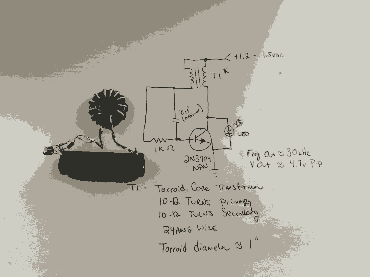
cellular phone calling detector circuit schematic
The circuit operates on the principle of electromagnetic induction, where the sensor coil L1 picks up the electromagnetic waves generated by the cellular phone when a call is received. The coil is tuned to the specific frequency range of the phone's signal, ensuring optimal sensitivity and responsiveness to incoming calls.
Upon detection of the electromagnetic field, the circuit activates a light-emitting diode (LED) to provide a visual indication of the incoming call. The LED flashes at a rate that can be adjusted based on the circuit design, allowing for customization of the visual alert.
Key components of the circuit include the sensor coil L1, which is typically constructed using insulated copper wire wound around a non-conductive core. The circuit may also incorporate a transistor or operational amplifier to amplify the signal from the coil, ensuring reliable detection of the phone's electromagnetic emissions. Additionally, resistors and capacitors may be used to filter noise and stabilize the circuit operation.
Power for the circuit can be supplied by a small battery or a USB power source, depending on the design requirements. The compact size of the circuit allows for easy integration into various environments, making it a versatile solution for users who may need a discreet alert system for incoming calls.
Overall, this circuit provides an effective solution for alerting users to incoming calls without relying on the traditional ringer of a cellular phone, enhancing usability in situations where sound notifications may be impractical.This circuit was designed to detect when a call is incoming in a cellular phone (even when the calling tone of the device is switched-off) by means of a flashing LED. The device must be placed a few centimeters from the cellular phone, so its sensor coil L1 can detect the field emitted by the phone receiver during an incoming call..
🔗 External reference
Related Circuits
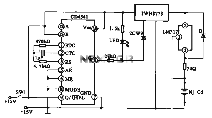
A constant current charging circuit with a long delay is implemented using the CD4541, which constitutes a constant current charging circuit suitable for Ni-Cd batteries. Upon powering on, the CD4541 output at pin high activates the TWH8778 electronic switch,...
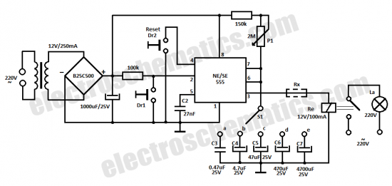
This time delay relay circuit is constructed using the NE/SE555 integrated circuit, manufactured by Intersil, which incorporates a precision timer. The circuit exhibits stability against temperature variations of 0.00. The NE/SE555 timer IC is a versatile device widely used in...
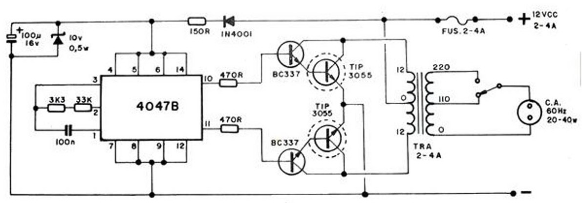
The converter transforms 12 VDC to 220 VAC, allowing for the conversion of 12 volts DC into 220 volts AC. The circuit diagram provided illustrates a simple converter circuit. This DC to AC converter can supply voltage for a...
In the previous post, the primary principles of the switching power supply were discussed. Essentially, an oscillator drives a transformer with a ferrite core at a relatively high frequency, thereby minimizing the size, weight, and cost of power supplies....
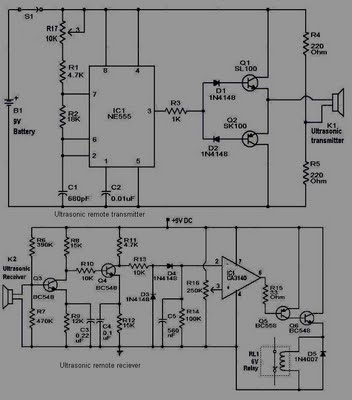
This circuit is straightforward and well-defined. The transmitter operates at 9 volts, while the receiver circuit functions at 5 volts. The transmitter utilizes a 555 timer and two SL100 transistors to perform its function. The receiver incorporates a small...

This circuit utilizes a 4049 integrated circuit (IC) to control a 2N2222 switching transistor. The transistor, in turn, drives a piezo transducer known as crystal 1. The circuit design begins with the 4049 IC, which is a hex inverter capable...
Warning: include(partials/cookie-banner.php): Failed to open stream: Permission denied in /var/www/html/nextgr/view-circuit.php on line 713
Warning: include(): Failed opening 'partials/cookie-banner.php' for inclusion (include_path='.:/usr/share/php') in /var/www/html/nextgr/view-circuit.php on line 713