
The Joule Thief circuit
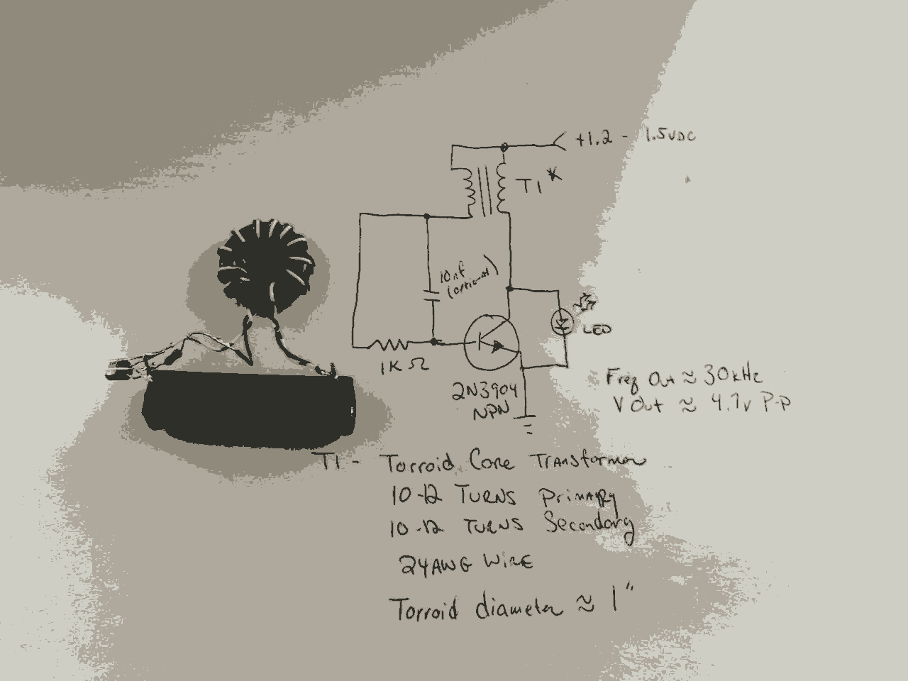
The circuit design for driving a white LED using a switching power supply involves several key components: an oscillator, a transformer with a ferrite core, a rectifier, and a current-limiting resistor. The oscillator generates a high-frequency square wave signal, which is fed into the primary winding of the transformer. The ferrite core of the transformer enhances the efficiency of energy transfer, allowing for a compact design.
The transformer steps up or steps down the voltage as needed, depending on the specifications of the LED. The output from the transformer is then passed through a rectifier, typically a diode bridge, to convert the AC signal into a DC signal suitable for powering the LED. Following the rectification, a current-limiting resistor is included in series with the LED to ensure that the current flowing through the LED does not exceed its maximum rating, thus preventing damage.
In addition to these components, filtering capacitors may be used at the output to smooth the DC voltage, providing a more stable power supply to the LED. This configuration not only enhances the performance of the LED but also contributes to the overall efficiency of the power supply by reducing losses associated with heat and electromagnetic interference.
The use of a switching power supply for LED applications is advantageous due to its ability to operate efficiently at high frequencies, which allows for a reduction in the size and weight of the overall power supply system. This makes it particularly suitable for portable and compact electronic devices that require effective lighting solutions.In the last post I discussed some of the primary principals of the switching power supply. Essentially an oscillator drives a transformer with a ferrite core at a relatively high frequency, thus minimizing the size, weight, and cost of power supplies. In this project we use the same principals to drive a white LED. 🔗 External reference
Related Circuits
This circuit is designed to drive a total of 42 LEDs, assuming a forward voltage of approximately 2.2V per LED and a forward current of around 21mA for adequate brightness. If the specifications of the LEDs differ significantly, modifications...
The circuit diagram of a simple capacitance meter is presented here. The primary component of this circuit is the frequency-to-voltage converter. The simple capacitance meter circuit utilizes a frequency-to-voltage converter as its central element to measure capacitance values. This circuit...
A small delay circuit is required to produce a pulse for a cell phone vibrational motor every 0.75 seconds, with an adjustable delay time ranging from 4 to 10 seconds. The circuit will be powered by a 9-volt battery. To...
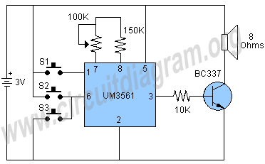
The circuit under discussion is a four-siren sound generator utilizing the UM3561 integrated circuit (IC), which is a low-power CMOS device. Four distinct sounds can be generated by activating switches S1, S2, and S3. This circuit is versatile and...
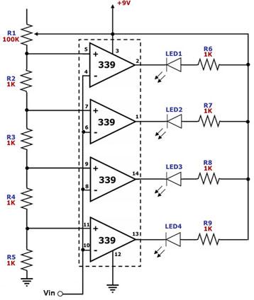
This circuit is designed as a simple LED bar graph voltmeter. Each operational amplifier in the LM339 quad package functions as a comparator, comparing the input voltage (Vin) to a series of fixed voltage levels that are proportional to...
Hello everyone. I need some help. I have constructed a PWM and PPM circuit. The output is functioning smoothly, but I am experiencing some problems and I am not very experienced. The PWM (Pulse Width Modulation) and PPM (Pulse Position...
Warning: include(partials/cookie-banner.php): Failed to open stream: Permission denied in /var/www/html/nextgr/view-circuit.php on line 713
Warning: include(): Failed opening 'partials/cookie-banner.php' for inclusion (include_path='.:/usr/share/php') in /var/www/html/nextgr/view-circuit.php on line 713