
Ultrasonic Remote Control Circuit
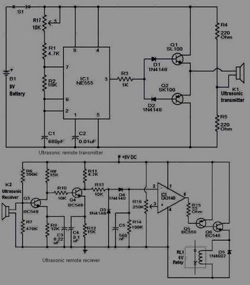
The circuit design features a transmitter and receiver system that operates at different voltage levels, specifically 9 volts for the transmitter and 5 volts for the receiver. The transmitter employs a 555 timer integrated circuit, which is widely utilized for generating precise timing pulses and oscillations. This timer is configured in astable mode to produce a square wave output, which is essential for modulating the signal.
To amplify the output from the 555 timer, two SL100 transistors are used in a push-pull configuration. This setup enhances the current driving capability of the transmitter, allowing it to effectively transmit signals over a distance. The choice of SL100 transistors, known for their high gain and frequency response, ensures robust performance and reliability in signal transmission.
On the receiving end, a small relay is implemented to control the desired application or load. The relay acts as an electrically operated switch, which is triggered by the incoming signal from the transmitter. When the relay is activated, it can control higher power devices or circuits, making it versatile for various applications, such as turning on lights, motors, or other electronic devices.
Overall, this circuit design demonstrates a practical application of basic electronic components to achieve wireless communication and control, showcasing the effectiveness of the 555 timer, transistors, and relays in circuit design.This circuit is as shown, simple and clear. The transmitter needs 9 volts and the receiver circuit needs 5 volts. The transmitter uses the 555 timer and two SL100 transistors to make the job. The receiver needs a small relay to control the desired job. 🔗 External reference
Related Circuits
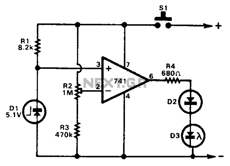
The 741 operational amplifier can function as a voltage comparator. It features a non-inverting input and a Zener-controlled voltage source, with a reference voltage set at 5.1V. Resistor R2 is used to adjust the in-phase input voltage to half...
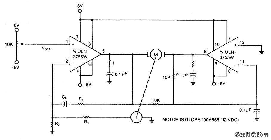
Power operational amplifiers provide precise speed control for DC motors. The circuit enables bidirectional speed control. The amplifiers' push-pull configuration guarantees a full rail-to-rail voltage swing (excluding the saturation drops of the output stages) across the motor in both...
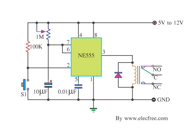
Many friends take an interest in the circuit involving the highly popular IC 555, which is an integrated circuit. This circuit sets the time in a basic manner. The IC 555 timer is a versatile and widely utilized component in...
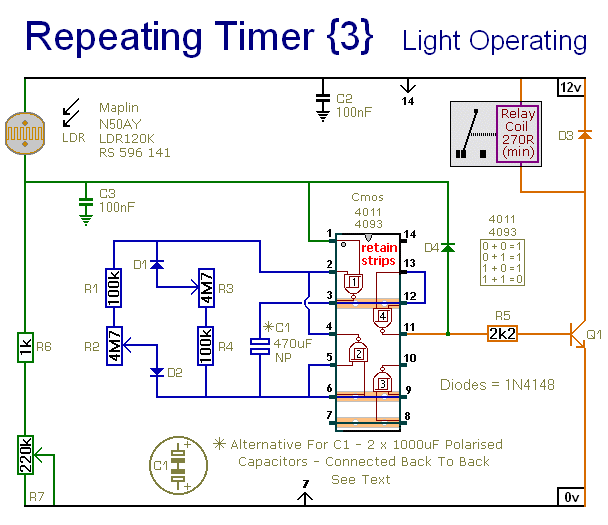
This circuit closely resembles Repeating Timer No. 2. However, the inclusion of a light-dependent resistor (LDR) allows the timer's operation to be confined to daylight hours. Resistor R7 enables the adjustment of the light level at which the timer...

This design schematic illustrates a Crystal Colpitts oscillator that can be implemented using a transistor and a parallel mode crystal. In this circuit, the crystal functions as an inductance. A large value capacitive divider is utilized between the gate,...
In certain locations near the reservoir or well, when the water level is constrained by the water towers, there is a need for simultaneous monitoring of the water towers and reservoirs as part of an automatic water control system....
Warning: include(partials/cookie-banner.php): Failed to open stream: Permission denied in /var/www/html/nextgr/view-circuit.php on line 713
Warning: include(): Failed opening 'partials/cookie-banner.php' for inclusion (include_path='.:/usr/share/php') in /var/www/html/nextgr/view-circuit.php on line 713