
ch laser
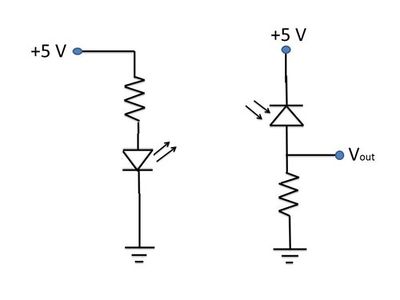
In this circuit configuration, the laser diode operates under forward bias conditions, which allows it to emit coherent light when current flows through it. The cathode of the laser diode (LDC) is connected to a driver transistor that plays a crucial role in regulating the current supplied to the laser diode. This regulation is essential for maintaining optimal performance and preventing damage due to overcurrent conditions.
The feedback network, which includes a photodiode, is integral to the operation of this circuit. The photodiode monitors the output light intensity from the laser diode and generates a corresponding current proportional to the light detected. This current is fed back into the driver transistor's control mechanism, allowing for real-time adjustments to the laser diode's operating current.
The driver transistor can be configured in various ways, such as using a bipolar junction transistor (BJT) or a field-effect transistor (FET), depending on the specific requirements of the application. The choice of transistor impacts the overall efficiency, response time, and stability of the feedback loop.
In summary, this configuration ensures that the laser diode operates efficiently and safely by continuously adjusting its current in response to changes in output light intensity, thus maintaining consistent performance across varying conditions. The design of the feedback network is critical, as it must be capable of responding quickly to changes in the photodiode's output to prevent fluctuations in the laser output.The laser diode will be forward biased and its cathode (LDC) will connect to a driver transistor &/or network to regulate the LD current based on the photodiode current (feedback network). 🔗 External reference
Related Circuits
Continuous wave (CW) operation is achievable with a current of up to 350 mA from a supply voltage range of 2 to 6 V. The system supports TTL modulation frequencies of up to 10 kHz, with an adjustable duty...
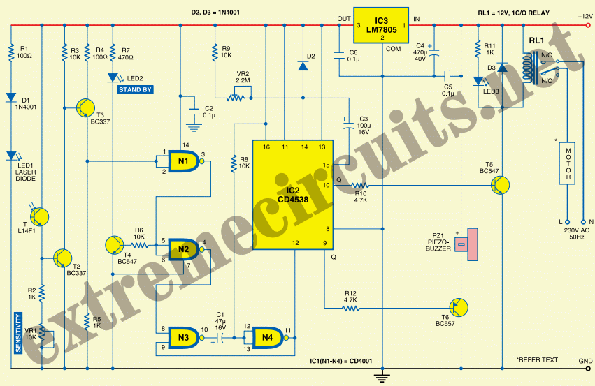
One day, an individual contemplates the necessity of purchasing an alarm installation system when it is possible to create one independently. The common rationale against this is a lack of skills or time. However, in this case, the preference...
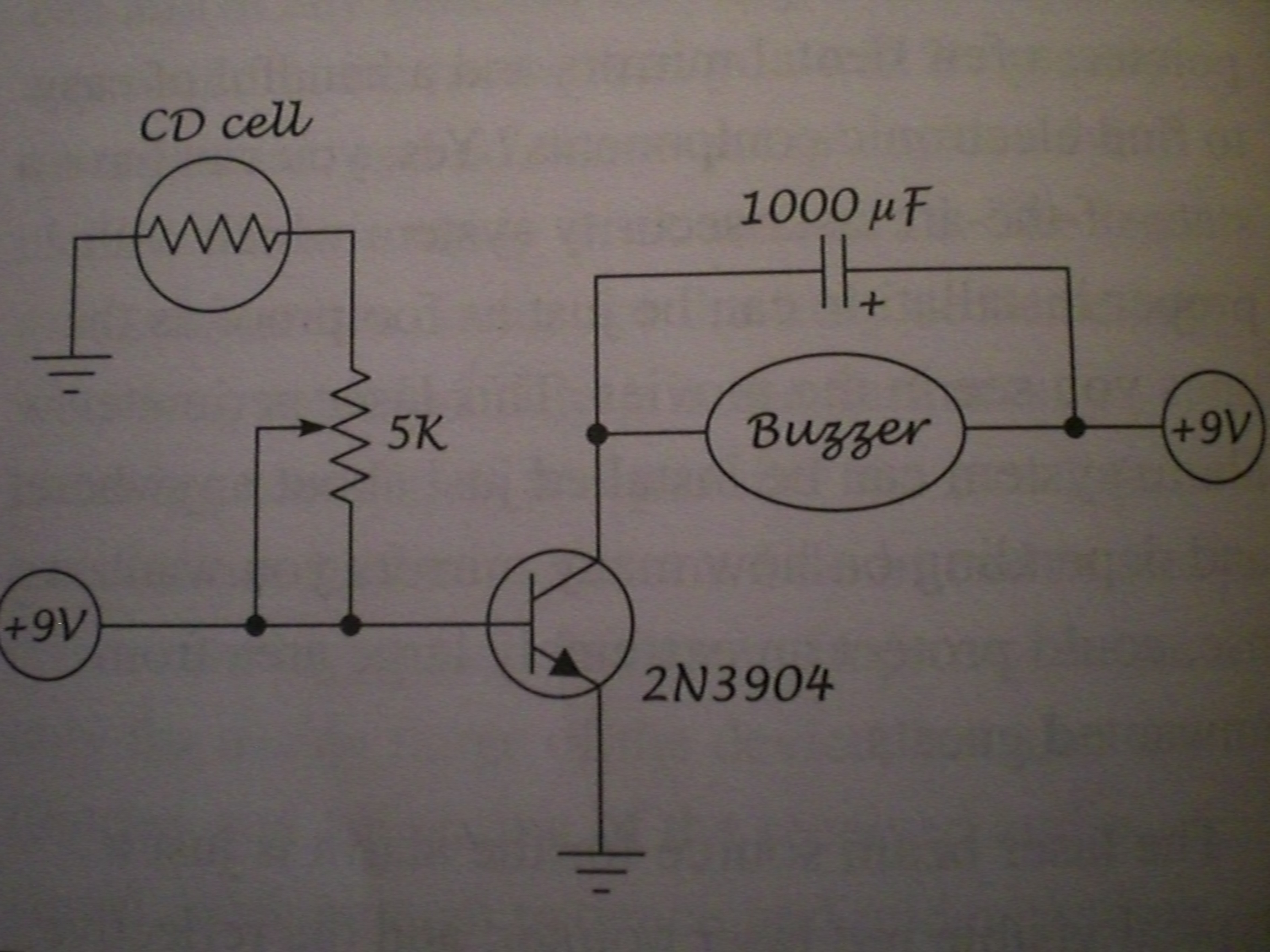
The following post illustrates a simple light-operated remote control circuit that can be activated by an ordinary flashlight or, more effectively, through a laser beam unit (keychain type). The Light Dependent Resistor (LDR) is connected between the base of...
This document tells about one of my experiments with semiconductor laser modules. I bought one semiconductor laser for all kinds of experiments. This TIM202 module is a small (38x14x14 mm) semiconductor laser module, similar to those types used in...
Free-space optical (FSO) communication utilizes light as a medium for data transmission. Communication was established between two computers using a laser, independent of any conventional communication methods. Text messages were sent from one PC to another using a system...
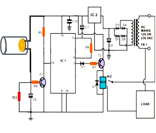
This automatic door opener can be constructed using readily available components. The electromagnetic relay at the output of this device can be utilized to control the door mechanism. The automatic door opener circuit is designed to facilitate the opening of...