
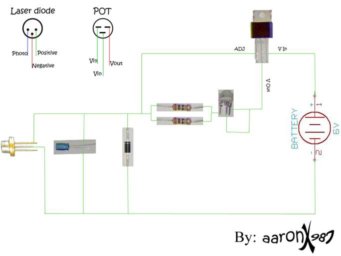
Laser Data Link schematic
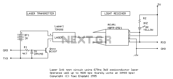
The circuit described utilizes a TIM202 semiconductor laser module, which operates at a voltage of 3V and a current of 45mA, emitting a laser beam at a wavelength of 670nm with an output power ranging from 3 to 5mW. This module can be effectively modulated for data transmission by employing a transistor that controls the laser's on/off state. The proposed laser data link requires a compatible receiver, for which the HBFR-2521 fiber optic receiver module has been selected due to its specifications supporting 665nm wavelength and a data rate of up to 5 Mbit/s.
The overall setup involves connecting the laser module to a power source, and the output is directed towards the HBFR-2521 receiver positioned several meters away. The receiver is connected to a computer's RS-232C serial port, facilitating communication through a standard serial interface. The circuit has demonstrated effective communication at rates up to 9600 bps, although it does not fully comply with RS-232 specifications. It has been noted that the performance may improve with short cable lengths.
Powering the circuit can be achieved using two AA batteries in series, providing a total of 3V, supplemented by an external 5V source for the receiver, drawing a current of approximately 20mA. The estimated cost for building this circuit is around $80, with an additional $80 required for a second unit to establish a full bidirectional communication link.
Considerations regarding safety are significant due to the potential harm from direct exposure to the laser beam. Therefore, appropriate precautions should be taken when operating the laser module. The reliability of the circuit has only been tested over short distances, and long-term performance remains unverified. Additionally, the testing revealed that the laser module's inherent design, which includes capacitors for power supply stabilization, may limit its switching speed, impacting data transmission performance.
For practical applications, this circuit can be utilized for experimental wireless communication, interfacing with standard PC serial ports, and is compatible with various communication software that operates at the supported RS-232 speeds, up to 9600 bps, without the need for handshaking lines.This document tells about one of my experiments with semiconductor laser modules. I bought one semiconductor laser for all kinds of experiments. This TIM202 module is a small (38x14x14 mm) semiconductor laser module, similar to those types used in laser pointers. It takes 3V 45mA and outputs 3-5mW 670nm laser beam. One evening I got an idea to make a simple laser data link using this semiconductor laser module and some kind of receiver.
Laser module can be easily modulated by switching it on and off using one transistor. I thought that receiving can be done easily with a one simple phototransistor circuit. I tested one simple circuit, but it did not work satisfactory. Then I got an idea to use ready-made receiving modules. I took out one HBFR-2521 fiber optic receiver module from my junk box. I checked the data of that module and found it to meet my needs: module is designed for 1 mm plastic fiber cable, module is designed for 665nm wavelenght and it can operate up to 5 mbit/s. I started to test the system using computer. I connected the circuit to the RS-232C serial-port if my PC and placed the receiver and transmitter few meters away from each other.
I started a communications program and tried the circuit with different communication speeds. Circuit performance: Seemed to work up to speeds of 9600 bps at distances of few meters. Circuit output does not fully meet the RS-232 specs but seems to work on typical PC RS-232 ports if short cables are used. Availability of components: Original components might be hard to get. Laser modules are now quite widely available but the suitability of other modules for this application is not known (some laser modules might performace poorly).
Design testing: Simple short experimenting over distances of few meters. Long term reliabity of this circuit is not tested. Applications: Esperimental wireless communications using laser, connects to standard PC serial port, can be used with almost any communication program which uses any RS-232 speed this circuit can handle (max 9600 bps) and does not need then handshaking lines Power supply: 2 x 1.5V AA batteries (70 mA current), external +5V source (20 mA current) Estimated component cost: this circuit $80 ($160 for two needed for real bidirectional communication link) Safety considerations: Circuit uses laser radioation which can harm your eyes if you look directly to the laser beam. No special electrical safety considerations. The reason why my system did not go must be in the laser module I was using, because the receiving module is capable for 5 mbit/s communication speeds.
It is not fast enough to follow fast signals just by switching the power on and off. I never tested the signal with oscilloscope to see if laser module was slow in starting or stopping. To make sure that the slow component was laser, I tested the circuit also with original LED transmitetter and there were no speed problems either in hardare or software. The software I used were my own RS-232 speed tester program and Telemate terminal program both running running under MS-DOS.
I have later found out that most laser modules have capacitors to filter power supply noise and switch glitches. These capacitors limit the switching speed of the laser module, but they are necessary to preserve the laser diode which can be easily damaged.
Before trying the HBFR-2521 fiberoptical receiverr module I tried to use Simple infra-red detector as the detector /that circuit was also sensitive to visible light). That circuit did not give any useful results because it was too slow. I thought that using simple this type prototransistor circuit were not usable in this application.. Uday Kamath repoerted me that he got good results up to 9600 bps using the following receiving circuit.
The circuit it gives out 0 and 5 volts which is not compatible with RS232. The circuit must be followed with MC1488 (or some other) rs232 driver to convert this to RS232. I have not tried this circuit, but the idea seems to be worth to try. 🔗 External reference
Related Circuits
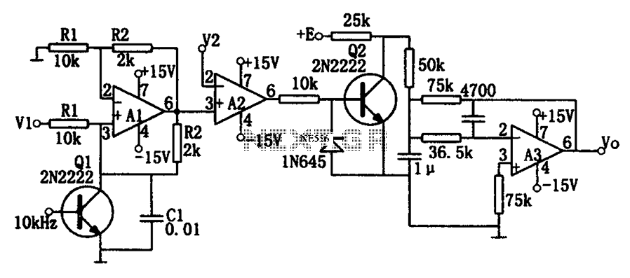
As illustrated in the dividing circuit diagram, A1 consists of a voltage-controlled current source, A2 functions as a voltage comparator, and A3 is configured as an active low-pass filter. When the time constant R1C1 is equal to the clock...

The lower schematic represents a standard bidirectional rectifier along with capacitors and a 7805 voltage regulator, which provides a stable 5V source to power the electronic components of the frequency counter. A fuse is included for security purposes. The...
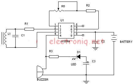
Metal detector schematic circuit using CS209A and a few electronic components. The metal detector circuit utilizing the CS209A integrated circuit is designed to detect metallic objects through the principle of electromagnetic induction. The CS209A is a specialized IC that facilitates...
There are at least three different versions of this circuit. The first DM-2 version utilized the MN3005 BBD and the MN3101 Clock Driver IC (PCB marking: ET5214-510). Later, the clock driver was changed to the MN3102, and the BBD...
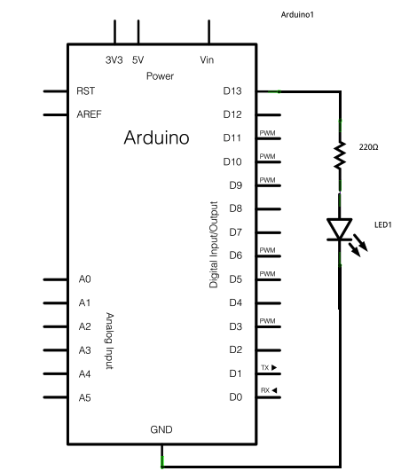
To construct the circuit, connect a 220-ohm resistor to pin 13. Next, connect the longer leg of an LED (the positive leg, known as the anode) to the resistor. The shorter leg (the negative leg, referred to as the...
A new user expresses interest in lasers and has purchased an inexpensive red laser pointer and LED light combination keychain. The red laser pointer and LED light combination keychain is a compact and versatile device that serves multiple functions. The...