
Laser-Guided Door Opener

The automatic door opener circuit is designed to facilitate the opening of a door without physical contact, enhancing convenience and accessibility. The primary components of this circuit include a power supply, an electromagnetic relay, a control switch, and a sensor (such as an infrared or ultrasonic sensor) to detect the presence of an individual approaching the door.
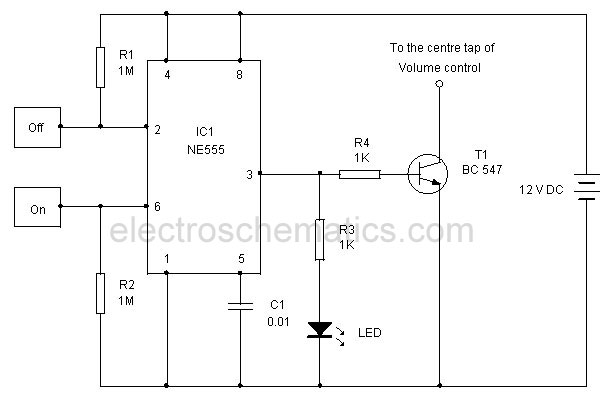
The power supply provides the necessary voltage and current to operate the circuit. A typical configuration might use a 12V DC power supply, which is sufficient for most electromagnetic relays. The relay acts as a switch that can control higher voltage loads, such as the door motor or locking mechanism, based on the input from the control switch or sensor.
The sensor is positioned near the door to detect motion. When an individual approaches, the sensor sends a signal to the control circuit. This signal activates the electromagnetic relay, which closes the circuit and powers the door mechanism, allowing it to open. The relay is selected based on the load it needs to control; for instance, a relay rated for at least 10A at 120V AC would be suitable for most standard door motors.
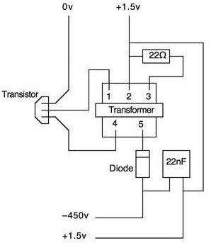
In addition to the basic components, it is advisable to include a diode in parallel with the relay coil to prevent back EMF (electromotive force) when the relay is deactivated. This protection is crucial to ensure the longevity of the control circuit. A resistor-capacitor (RC) delay circuit can also be integrated to provide a delay in the operation of the door, allowing it to remain open for a predetermined time before closing automatically.
Overall, this automatic door opener circuit is an efficient solution that can be easily tailored to various door types and environments, ensuring reliable operation with minimal human intervention.This automatic door opener can be made using readily available components. The electromagnetic relay at the output of this gadget can be used to control t.. 🔗 External reference
Related Circuits
Modify it to click and latch a relay when the button is pressed from anywhere in the house. Additionally, if possible, unlatch the relay when pressed again. A flip-flop circuit may be created to take the first signal and...
This article outlines a straightforward and effective method for deterring intruders. While alternative methods exist, this approach is suitable for office pranks and general amusement. The project necessitates a basic understanding of electronics and circuitry, including the ability to...
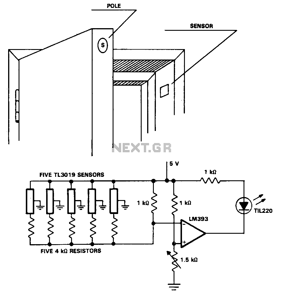
The TL3019 device activates, or goes low, when a south pole of a magnet approaches the chip face. In this example, there are five doors, each equipped with a magnet embedded in its edge, with the south pole facing...
It is a relatively simple circuit of electronic lock of safety with code of 7 digits. It should is given attention in the time that will be stepped the keys, that shape code and it does not exist it...
This touch-controlled musical bell circuit generates a musical tone whenever someone touches the designated touch point (TP). The circuit operates using two AA batteries and produces sufficient sound output. It utilizes the UM3481 integrated circuit, which is commonly employed...
This very simple and self-powered device was conceived to allow a person to monitor if someone has rung his home door-bell when he was out. As most door-bells use 12Vac supply, the circuit must be simply connected to the...
Warning: include(partials/cookie-banner.php): Failed to open stream: Permission denied in /var/www/html/nextgr/view-circuit.php on line 713
Warning: include(): Failed opening 'partials/cookie-banner.php' for inclusion (include_path='.:/usr/share/php') in /var/www/html/nextgr/view-circuit.php on line 713