
Burglar alarm circuit
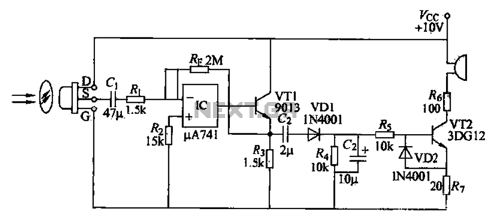
The described burglar alarm circuit is designed to detect movement using a pyroelectric sensor, specifically the IRA-E100SZI model. This sensor is sensitive to infrared radiation emitted by human bodies, making it effective for security applications. Upon detecting movement, the sensor activates an electric buzzer alarm, which serves as an alert mechanism.
The signal from the sensor is initially an AC signal, which is then amplified using an AC amplifier. This amplification is crucial because the output signal from the pyroelectric sensor is typically weak. Following amplification, the signal is processed through a rectifier circuit, which converts the AC signal into a DC signal suitable for further processing. This DC signal is used to drive two transistors, VT1 and VT2, which act as switches in the circuit. When activated, these transistors allow current to flow to the piezoelectric buzzer, producing an audible alarm sound.
The circuit design recognizes the need for significant amplification of the initial signal. A single-stage amplifier may not provide sufficient gain, particularly in environments with background noise or other interference. Therefore, a multi-stage amplifier configuration is recommended to achieve the necessary gain of approximately 70dB. This multi-stage approach ensures that even weak signals generated by body movement can be effectively amplified to trigger the alarm.
In scenarios where the movement detection signal is particularly weak, the integration of an optical zoom system can enhance the detection capability. This system can focus on specific areas, improving the sensor's ability to detect subtle movements. The overall design of the burglar alarm circuit prioritizes reliability and responsiveness, making it suitable for residential and commercial security applications.A simple burglar alarm circuits, sensors pyroelectric sensor IRA-E100SZI. When human movement is detected, the pressure on the electric buzzer alarm whistle. Sensor receives si gnals via AC amplifier, and then by the rectifier circuit into a DC drive transistor VT1, VT2 when turned on. Piezoelectric buzzer alarm. Several nearby Hertz gain amplifier circuit requires about 70dB, single-stage amplifier is not enough, it can be multi-stage amplifier to ensure the necessary gain.
When the input signal is generated by the body movement is very weak, the general use of the optical zoom system.
Related Circuits
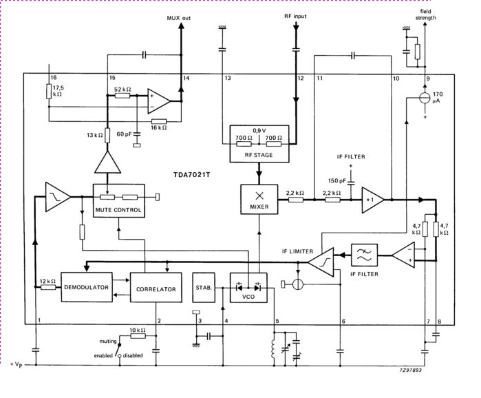
The TDA7021T integrated radio receiver circuit is designed for portable radios, both stereo and mono, where minimal peripheral components are essential for achieving small dimensions and low cost. It is fully compatible. The TDA7021T is a highly integrated radio receiver...
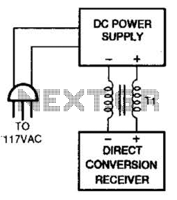
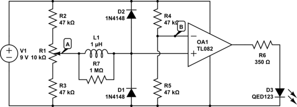
One solution for AC power line hum and ripple, which is caused by leakage current, is to utilize a well-regulated and filtered 9 to 18 VDC power supply that incorporates a balancing choke (Tl in this illustration) between the...
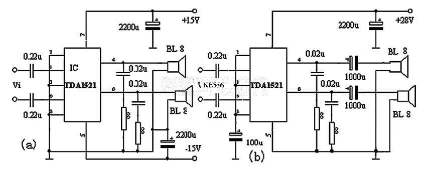
The TDA1521A amplifier circuit is designed for high-fidelity applications with minimal external components. It is suitable for powering Walkman devices or transforming low-powered computer speakers. The TDA1521A comes in a nine-pin single in-line plastic package and offers output power...
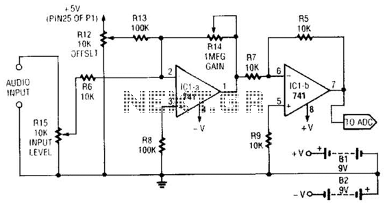
This simple general-purpose driver for an analog/digital converter uses two 741 IC devices with adjustable gain and offset. Other op-amps might be substituted, but some circuit adjustments might be needed. The circuit consists of two operational amplifiers (op-amps) from the...
The circuit above is a canonical AC coupled common emitter amplifier, which is typically used as a linear amplifier rather than a switch that activates when the input exceeds a certain level. The AC coupled common emitter amplifier is...
This is the timekeeping test circuit. It includes a one-transistor circuit to switch in the 5V power supply when present and drop back to the 3V battery the rest of the time. That loop of blue wire-wrapping wire is...
Warning: include(partials/cookie-banner.php): Failed to open stream: Permission denied in /var/www/html/nextgr/view-circuit.php on line 713
Warning: include(): Failed opening 'partials/cookie-banner.php' for inclusion (include_path='.:/usr/share/php') in /var/www/html/nextgr/view-circuit.php on line 713