
chip programmer
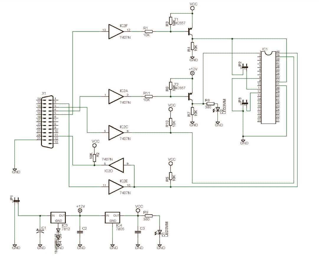
The electronic schematic for this heating control system consists of several key components. The primary unit, the programmer, is equipped with a microcontroller that processes user input from the front panel and serial interface. This microcontroller is responsible for managing the logic of the heating and hot water control based on the programmed schedule. The programmer interfaces with two relays, each controlling the heating system and hot water supply, respectively. These relays are activated based on the output signals from the microcontroller, allowing for independent control of each function.
Power is supplied to the programmer and relay units through a low-voltage power supply, ensuring safety and compatibility with household wiring. The communication between the programmer and the relay units is established via a six-wire connection, which includes power, ground, serial data, and relay control signals. This configuration allows for flexibility in installation, as the relay unit can be positioned near the boiler, while the programmer can be located in a more accessible area within the home.
The software running on the microcontroller is designed to handle user inputs, manage the heating schedule, and maintain the current state of the system even after power interruptions. The use of NVRAM for storing settings ensures that the system can recover from power failures without losing critical configuration data. The serial terminal interface provides an additional layer of control, allowing for remote adjustments and monitoring from a PC, enhancing the overall user experience.
In summary, the heating control system combines hardware and software components to provide an efficient and user-friendly solution for managing domestic heating and hot water supply, with features that cater to both remote and local operation.This project has come about from my desire to control my home heating from work. As I have a VPN between work and home a straightforward relay controlled from a PC would seem the easiest solution. However I also wanted a control unit that I could operate in the house without resorting to the computer.
For example, I get up late and the heating is off, I just want to hit a button and turn it on. In fact the programmer shown on this page is now next to my bed so I can turn the heating on before I get up late, and also switch it off if I turn in early, which helps save on the fuel bills J This programmer has been designed for use with a domestic heating boiler. It provides outputs via two relays to control the supply of Hot Water and Heating. There are 10 program entries available and each one can control the heating and water independently. The programmer allows manual advance of the heating and water and disabling of program control, useful if you`re going away for a few days and want to leave the heating and water off.
As well as providing normal front panel switch control of the heating and water, the programmer also features a serial terminal interface that allows it to be operated remotely from a PC running a Terminal Emulator. The program entries can be set to switch weekdays only, weekends only or everyday but not individual days.
I believe a programmer that can switch weekdays or weekends is a 5/2-day programmer so I would call mine a 5/2/7 day programmer since it can do the whole week as well. However, a 7-day programmer is one that can do individual days so I`ve settled on calling mine an Enhanced 5/2-day programmer.
The programmer and boiler control relays are contained in separate units so that the relays can be located close to the boiler while the programmer itself can be located anywhere in the house using low voltage connections back to the relay unit. The connection between the programmer and relay unit requires six wires for power, serial data and relay controls making it possible to use 6-core alarm cable or, as I have done, operate it over the CAT5 UTP cabling installed throughout my house.
Of course it`s quite simple to build it as a single unit if that suits the application. There is also no reason why you can`t make the serial interface connection local to the programmer in which case you only need 4 wires for power and relay controls. If you don`t require the remote computer CLI the programmer is fully functional using just the front panel and likewise, if the front panel isn`t required, it can be fully controlled from the serial interface and the LCD and switches omitted from the hardware.
The software is fully functional and the system as described on this web page is currently working with my domestic heating system. I`ve been using prototypes since March 2005. The latest code, Version 2. 0. 2, has been running since 28 May 2005. As of 25 March 2014 it`s still working and has proved to be 100% reliable. This is the final version of the code. I`m not going to develop it any further since the programmer now implements all the features I want and works as I intended.
I will do maintenance code releases to fix any software related bugs / issues reported to me. The current relay output and manual mode settings are stored in NVRAM. In the event of a power failure these are restored when the power resumes. If a programmed setting should have applied at a time during the power outage, it will not get applied when the power is restored. The saved settings that were active at the time of the power failure will be reapplied. When in front panel setup mode, no programmed outputs will be activated. If a programmed setting should have applied while the programmer was in setup mode, it will not get applied on exit.
On power up the programmer sends a VT100 [ESC] c command to the terminal to reset it. This may cause extraneous characters to be displayed or 🔗 External reference
Related Circuits
This programmer was designed in view of to be flexible, economical and easy to built, the programmer hardware utilizes the standard TTL series parts and no special components are used. The programmer is interfaced with the PC parallel port...
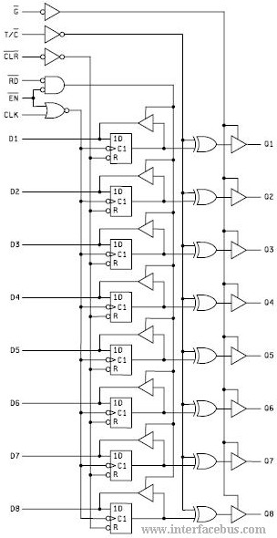
The 74ALS996 component is designed for the commercial temperature range, while the 54ALS996 is available for operation within the military temperature range. Although both components are typically offered in the same package styles, this may change as the usage...
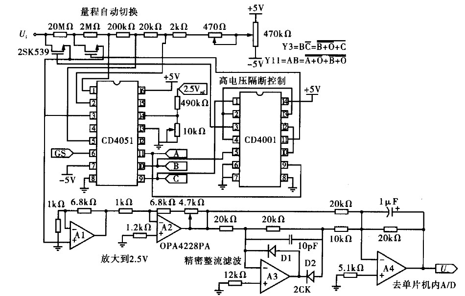
Voltage measurement is a fundamental aspect of electronic technology today, with increasing demands for accuracy and functionality in instruments. This is particularly critical when measuring signals with significant phase differences, as it is essential to ensure the accuracy of...
A guitar to MIDI interface was designed to serve as an interface between guitar playing and MIDI control of external hardware and software. This document describes the details of the design, experimentation, implementation, and final outcome of the project....
For relatively small projects with fewer pins than the ATmega328, the ATtiny series, specifically the ATtiny45 or ATtiny85, is a good choice due to its compact physical size. The ATtiny series microcontrollers, particularly the ATtiny45 and ATtiny85, are designed for...
The SCHAER+ programmer is a programmer for PIC18 family from a PC parallel port (LPT). It is derived from the SCHAER programmer I used to download my projects in PIC1684. The SCHAER+ programmer should be improved to use a...