
ATMEL 89C Series Flash Programmer

The Flash Programmer circuit is designed to provide a straightforward and cost-effective solution for programming flash memory devices using a PC's parallel port. The use of standard TTL (Transistor-Transistor Logic) components ensures compatibility and ease of construction, making it accessible for hobbyists and engineers alike.
The circuit primarily consists of a few key integrated circuits and passive components that facilitate communication between the PC and the target flash memory. The central component, U1, functions as a data flow controller, managing the signals sent from the parallel port to the memory device. This IC is crucial for ensuring that the data is correctly interpreted and transmitted, allowing for reliable programming operations.
U3 serves a vital role in the circuit by latching the low-order address lines. This function is essential for addressing the specific memory locations within the flash device during the programming process. Proper latching of the address lines ensures that the programmer can access and write to the correct locations in the memory, which is critical for successful programming.
The design's flexibility allows it to interface with a wide range of flash memory types, making it a versatile tool for various applications. The straightforward nature of the circuit means that it can be assembled using commonly available components, thus minimizing costs and enhancing accessibility for users with different levels of expertise.
Overall, the Flash Programmer circuit is an efficient and economical solution for programming flash memory, leveraging the simplicity of TTL technology and the ubiquitous nature of the PC parallel port.This programmer was designed in view of to be flexible, economical and easy to built, the programmer hardware utilizes the standard TTL series parts and no special components are used. The programmer is interfaced with the PC parallel port and there is no special requirement for the PC parallel port, so the older computers can also be used with this programmer.
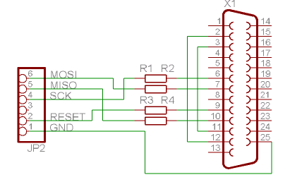
Figure 1 shows the circuit diagram of the Flash Programmer, the programmer is interfaced with the standard parallel port of the PC. As shown in the diagram U1 is used to control the data flow between controller and the pc, U3 latched the low order address
🔗 External reference
Related Circuits
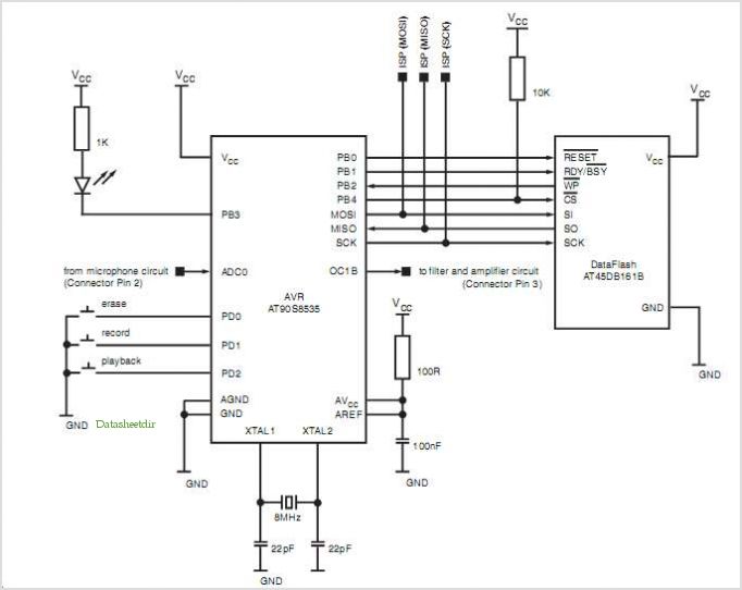
The Atmega 128 is similar to other AVR microcontrollers. It is in-system programmable (ISP). An earlier article discussed the AVR ISP programmer, which utilizes a 74HC244 buffer for safety when programming the AVR. However, if a programmer for the...
The Flash MC Programmer II is a rapid parallel port programmer designed for various 40-pin 8051 microcontrollers. The Flash MC Programmer II employs a parallel port interface to facilitate high-speed programming of 40-pin 8051 microcontrollers. This device is particularly advantageous...
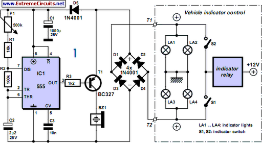
For bikers or scooter riders, it is easy to forget to cancel flashing indicators after turning without an audible reminder. Constantly checking indicator lamps is not practical; attention should remain on the road. The circuit presented here offers an...
The Z86E02 is one of ZiLOG's most popular Z8 One Time Programmables (OTPs). It features a 512-byte EPROM, 61 bytes of RAM, 14 I/O ports, a Watch-Dog Timer, Power-On Reset, a Low-Voltage Protection circuit, and an additional Timer. Notable...
This article discusses the Gadgets, Gizmos, and Arduino (ATMega328). The content is straightforward and informative. The components mentioned in this article can enhance the understanding of the subject. For instance, readers can find and purchase components such as the...
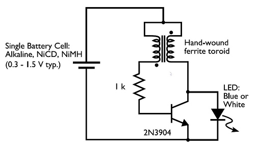
In the circuit diagram for the Joule Thief, the common point of the toroid is the connection at the top of the hand-wound ferrite toroid, located in the upper right of the diagram. This connection leads to the positive...