
ATtiny programmer using Arduino ISP

The ATtiny series microcontrollers, particularly the ATtiny45 and ATtiny85, are designed for applications where space is a constraint and minimal pin count is required. These microcontrollers are based on the AVR architecture and offer a range of features suitable for small-scale embedded projects.
The ATtiny45 has 8 pins, while the ATtiny85 has 8 pins as well but can be configured for more functionality through its flexible I/O options. Both microcontrollers operate at a voltage range of 2.7V to 5.5V and can run at clock speeds up to 20 MHz, making them efficient for low-power applications.
In terms of memory, the ATtiny45 has 4 KB of flash memory, 256 bytes of SRAM, and 128 bytes of EEPROM, while the ATtiny85 features 8 KB of flash memory, 512 bytes of SRAM, and 512 bytes of EEPROM. This memory capacity allows for the storage of small programs and data, making these microcontrollers ideal for tasks such as sensor interfacing, simple control systems, and low-power wireless applications.
The pin configuration includes digital I/O pins, analog inputs, and support for PWM outputs, enabling a variety of interfacing options. Additionally, both microcontrollers support various communication protocols, such as SPI and I2C, which facilitate integration with other devices and sensors.
Programming these microcontrollers is typically done using the Arduino IDE or Atmel Studio, which provides a user-friendly environment for code development. The compact size and versatility of the ATtiny45 and ATtiny85 make them suitable for applications in wearable technology, IoT devices, and other small electronic projects where size and power efficiency are critical.For relatively small (less number of pins than ATmega328) projects, ATtiny series, ATtiny45 or Attiny85 are good choice in terms of its physical size.. 🔗 External reference
Related Circuits

The circuit diagram represents an ultra-sensitive intruder alarm. A shadow from an intruder passing nearby is sufficient to trigger the alarm. The operational amplifier IC2 (uA 741) is configured as a sensitive comparator, with its set point determined by...
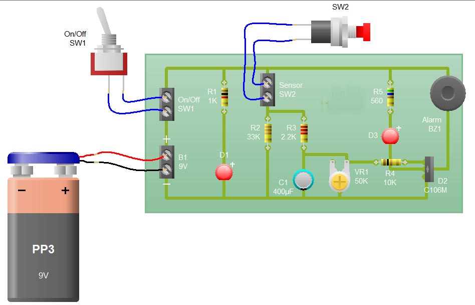
When the sensor switch SW2 is pressed, the LED D3 and the alarm are activated for a certain duration. The timing of the circuit is determined by the resistor R3 and capacitor C1. Additional details regarding the RC circuit...
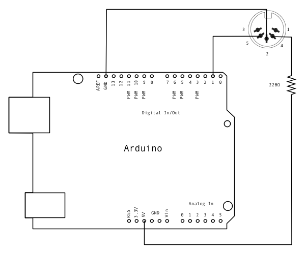
MIDI, or Musical Instrument Digital Interface, is a protocol designed for controlling synthesizers, sequencers, and various musical devices. MIDI devices are typically categorized into two main classes: controllers, which generate MIDI signals based on user input, and synthesizers, which...
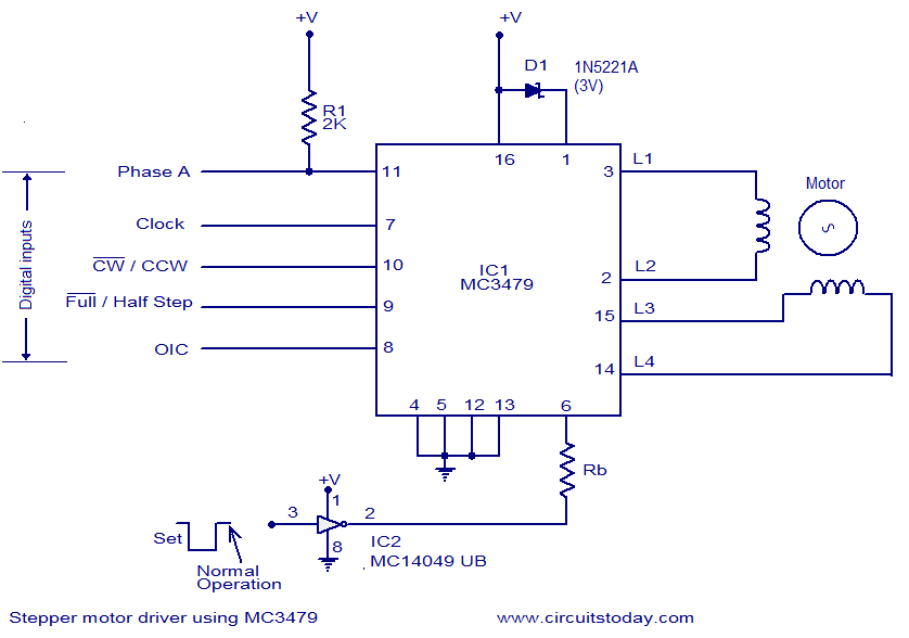
The circuit diagram presented is for a stepper motor driver utilizing the MC3479 integrated circuit from Motorola. The MC3479 is specifically engineered for driving a two-phase stepper motor in bipolar mode and is available in both standard DIP and...
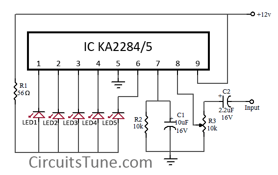
This is a simple circuit diagram of a 5-LED audio VU meter utilizing the ICs KA2284 or KA2285. The KA2284 and KA2285 are monolithic integrated circuits designed as logarithmic display driver ICs. They serve as bar-type display drivers for...
The back-to-back diodes are included because some radios generate high voltage transients when switching bands, which can cause the DFD to lock up, requiring a power cycle to reset. If the power for the backlit display is sourced from...