
Christmas lights consisting of a circuit diagram of optocoupler
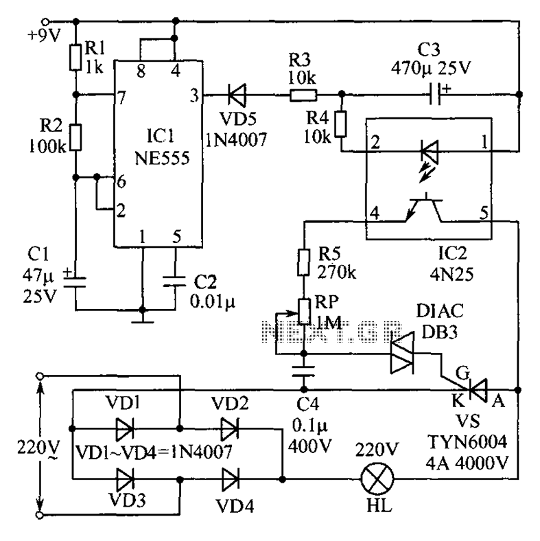
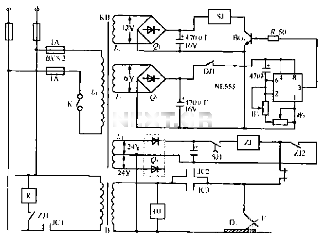
The described Christmas lights circuit utilizes an NE555 timer integrated circuit (IC1) configured in a non-stable mode to create a continuous oscillation that controls the brightness of the lights (HL). The circuit's operation begins when power is applied, allowing the timer to generate a square wave output. The frequency of this oscillation is determined by the values of resistors R1 and R2, along with capacitor C1, which set the timing intervals for the charging and discharging cycles.
As the output from pin 3 of the NE555 goes high, capacitor C3, which is connected to the circuit, begins to discharge through the optical isolator IC2 (CN25). This discharge process causes the brightness of the lights (HL) to decrease gradually. The optical isolator serves as a safety mechanism, ensuring that the high voltage present in the lighting circuit does not affect the low voltage control circuit.
Once the lights reach their minimum brightness, the NE555 timer output transitions low, allowing capacitor C3 to recharge. This recharging phase enables the lights to gradually brighten again, completing the cycle. The smooth transitions between bright and dim states create an aesthetically pleasing effect, ideal for festive decorations. The entire circuit is designed to provide a visually appealing illumination effect while ensuring reliable operation through the use of standard electronic components.
In summary, this Christmas lights circuit is an excellent example of utilizing basic electronic components to achieve a dynamic lighting effect, making it suitable for various decorative applications during the holiday season. As shown is a very attractive Christmas lights circuit. When the power is turned on, lights HL will gradually become brighter; when it reaches the brightest, it will automatica lly gradually darken; et brightness of the darkest time, will automatically brighten gradually, so repeated. Smooth the entire change process. Brightness change process depends on the charger lights HL capacitor C3 discharges. When IC1 (NE555) 3-pin output is high, the capacitor C3 begins to discharge through the IC2 (CN25) optical isolation, lantern HL brightness began to decline.
IC1 here set no stable oscillator whose frequency is determined by R1, R2 and C1.
Related Circuits
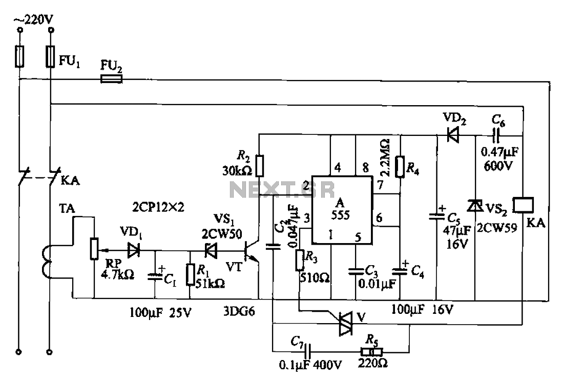
The 555 limit circuit, which is an integrated electrical circuit, is designed to manage large electrical loads. It automatically disconnects power when the load exceeds a predetermined threshold. Once the load is reduced below this threshold, power is restored...
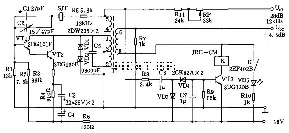
The circuit depicted is a 12 kHz intermediate frequency oscillator designed for an alarm system. It employs a variable feedback oscillation circuit where the oscillation frequency is primarily determined by a quartz crystal. Capacitors C1 and C2 are used...
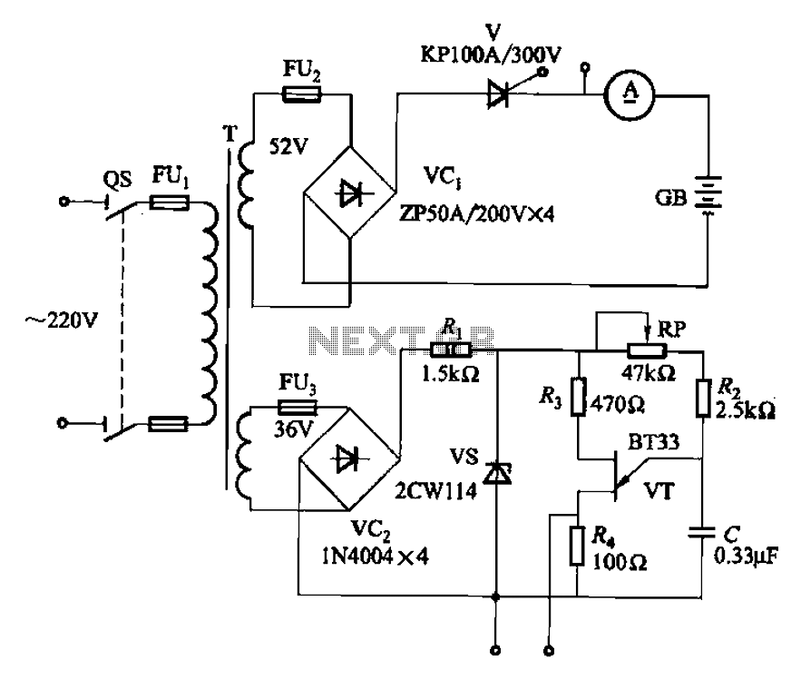
The adjustment potentiometer RP can modify the magnitude of the DC output voltage. The adjustment potentiometer, designated as RP, is an essential component in various electronic circuits, particularly in power supply systems and signal conditioning applications. It serves as a...
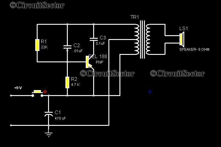
This circuit is a low-cost, one-touch doorbell using a Bel 188 transistor. It is likely one of the most economical bell circuits that can be constructed. The core component of this circuit is the output transformer from a push-pull...
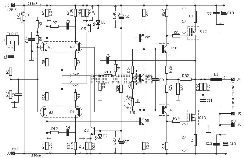
This HEXFET Audio Amplifier 65 Watts circuit diagram includes three circuit images. For a more comprehensive understanding, refer to the original post titled "HEXFET Audio Amp 65 Watts." The post not only provides circuit information but also includes a...
The NE555 timer circuit functions as a vibration generator. The input pin 3 produces pulse frequencies ranging from 5 to 20 Hz. The circuit includes a fan that operates within a bamboo enclosure. The barrel section is designed to...