
One group of integrated circuits using electrical circuit 555 when the load limit
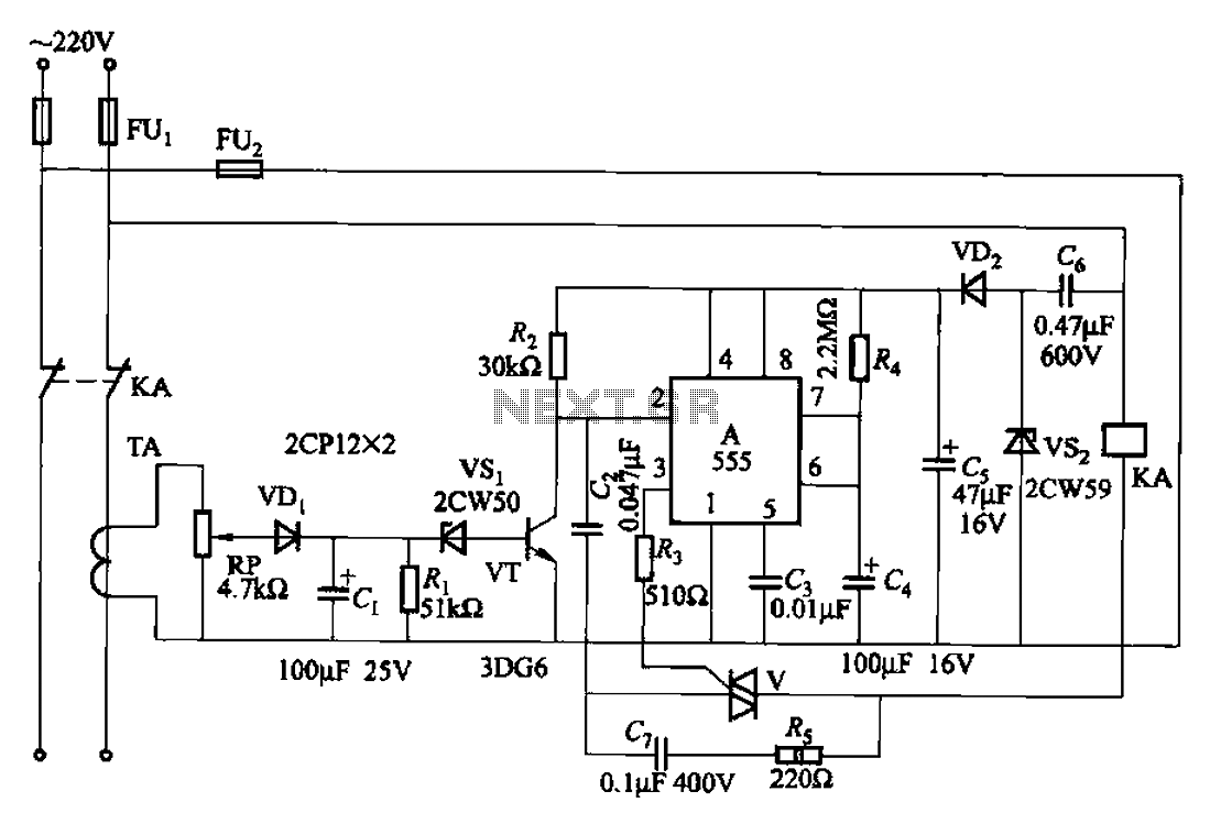
The 555 limit circuit is a practical application of the 555 timer IC in a load management scenario. This circuit can be particularly useful in preventing damage to electrical appliances or systems by limiting the current flow based on specific load conditions.
In its operational state, the circuit continuously monitors the load current. When the load current exceeds the set point, the circuit activates a relay or a switch to disconnect the power supply. This action protects the connected equipment from overheating or damage due to excessive current. The relay can be chosen based on the load requirements and should be rated appropriately to handle the maximum load current.
The configuration of the 555 timer in monostable mode allows for a single output pulse when triggered. The duration of this pulse is determined by the resistor R4 and capacitor C4 values, which define the time it takes for the circuit to reset and allow power to flow again after the load has dropped below the set threshold. The adjustment potentiometer RP provides flexibility in tuning this time delay, enabling the user to set it according to specific application needs.
When designing this circuit, careful consideration should be given to the selection of components, including the 555 timer, resistors, capacitors, and the relay. The circuit should be tested under various load conditions to ensure reliable operation and to fine-tune the delay settings for optimal performance. Additionally, proper heat dissipation measures should be implemented to maintain the integrity of the components during operation.
Overall, the 555 limit circuit serves as an effective solution for load management, enhancing the safety and longevity of electrical systems.555 limit when one group integrated electrical circuit load circuit is shown. It can limit the large load electric power. When the electricity load exceeds a set value, automat ically breaking power; when the load to be reduced to below the set value, it can automatically restore power. It uses capacitor step-down, using 555 IC A composition monostable delay circuit. Adjust R4, C4, can be changed variable delay time adjustment potentiometer RP, you can change the operation setting value.
Related Circuits

It is embarrassing to acknowledge that the blog post from April 29 contained several schematic errors of my own making, particularly in the variation of Morgan Jones's circuit. One of the resistor values was incorrect by a factor of...
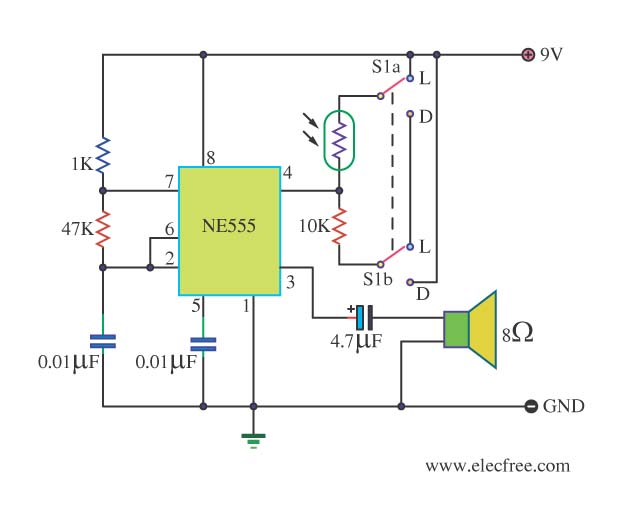
This circuit detects light and provides a voice warning. It responds to changes in light conditions, becoming active based on the position of switch S1. The circuit utilizes a light-dependent resistor (LDR) to sense ambient light levels. When the light...
Many applications require low-frequency signal generators that can deliver high-performance, high-resolution signals. This design idea presents a circuit that generates frequencies from 0 to 1 MHz, providing sinusoidal, triangular, and square-wave outputs with frequency resolution better than 0. A...
This circuit operates at potentially lethal 220V AC mains voltage. The circuit should be built and used only by individuals who know how to safely work with such dangerous voltages and how to construct the circuit to ensure safety....
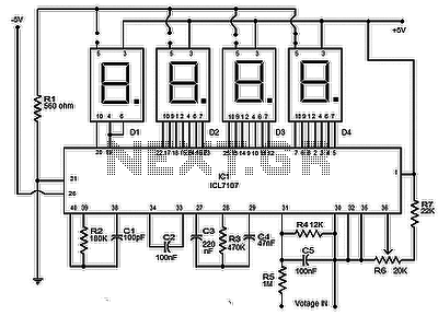
The circuit presented is a highly effective and precise digital voltmeter with an LED display utilizing the ICL7107 from Intersil. The ICL7107 is a high-performance, low-power, 3.5-digit analog-to-digital converter (ADC). This integrated circuit (IC) incorporates internal components such as...
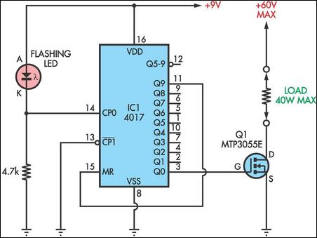
This circuit utilizes a flashing LED as the clock input for a 4017 decade counter. Typical flashing LEDs, such as the DSE cat Z-4044, flash at approximately 2Hz, causing the outputs Q0-Q9 to cycle at that rate. For instance,...