
A welding load automatic power-off circuit
The NE555 timer is a versatile integrated circuit commonly used for generating precise timing and oscillation applications. In this circuit, the NE555 is configured in astable mode, which allows it to continuously oscillate between high and low states, generating a square wave output. The frequency of this oscillation is determined by the values of the resistors (R1, R2) and the capacitor (C) connected to the circuit. The output frequency can be adjusted within the range of 5 Hz to 20 Hz by changing these component values.
The circuit's output, taken from pin 3 of the NE555, is used to drive a fan located in a bamboo enclosure. The design of the barrel section allows for easy integration of the required resistors and capacitors, ensuring that the circuit can be fine-tuned for optimal performance. A transistor is incorporated into the circuit to amplify the power output, enabling the fan to operate effectively under varying load conditions.
In addition to the basic oscillation functionality, the circuit includes two operational modes. The first mode is designated for standard fan operation, while the second mode is intended for bilge selection, which may be useful in maritime applications where water removal is necessary. The "withering contingent" mode is an additional feature that stabilizes the output frequency for specific applications.
The motor speed can be controlled dynamically based on the load it experiences, allowing for efficient operation. The circuit may also include a control segment designed for compact fluorescent lights, enabling it to manage the light's operation in conjunction with the fan's function. Overall, this NE555-based circuit is a well-rounded solution for applications requiring vibration generation and motor control.NE555 tour allows just as vibration. } E input pin 3 River) pulse frequency ult / 5 ~ 20Hz Fan Cave weeks bamboo. Barrel section to ridicule steep scheduled for R and C. Value. m transistor 1j and T} Hungary throw success rate system level power output fl1 sail. AJl and f can control the oscillation frequency of 555. There are "Shai fans" and "shift" models t bilge selection. "Withered contingent" mode is set f rinse certain frequency. Juice motor drawing to determine the speed. "Change" Bu marrow type the compact fluorescent Sichuan F1 motion control segment continued Ba f f Section vmiiJ pupil Cui motor speed.
Related Circuits
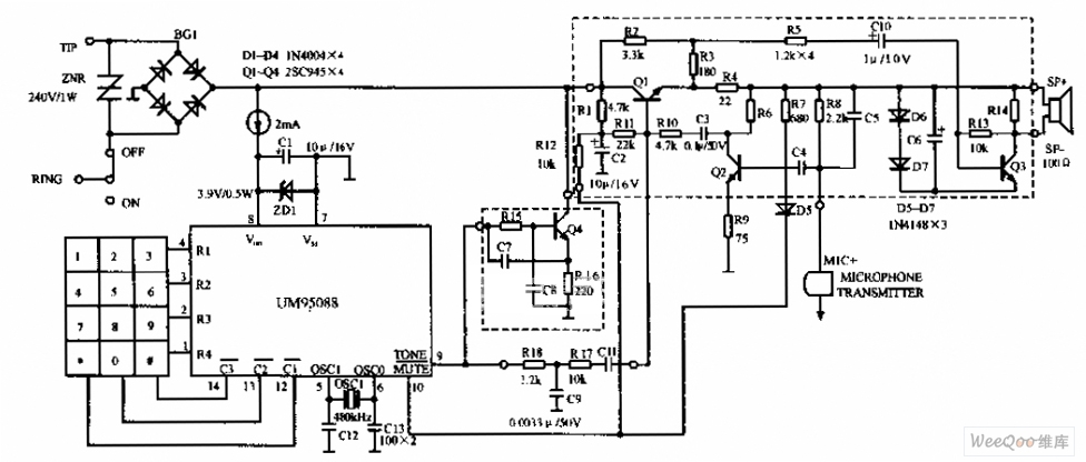
The UM95088 telephone circuit diagram is depicted in the image above. The UM95088 is a specialized integrated module designed for dual-tone multi-frequency (DTMF) telephone dialing. It utilizes CMOS technology and comes in a 14-pin dual-in-line package. The schematic for...

The duration for which the circuit remains active is determined by the time required for the stored electrical current to leak back into the circuit, which keeps the transistor and the entire circuit energized. A resistor is present that...
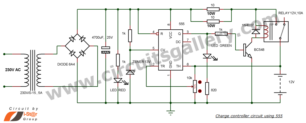
This is a simple DIY charge controller schematic created in response to a request from one of the readers on our Facebook page. The primary component of this automatic battery charger circuit is a 555 timer, which compares the...
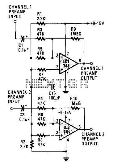
The circuit operates using two 741 operational amplifiers and achieves a gain exceeding 20 dB in each channel. Utilizing a higher-quality op-amp can improve the noise figure and bandwidth. Additionally, the circuit features a sharp roll-off at 20,000 Hertz. This...
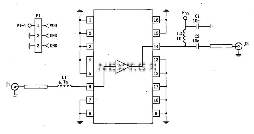
A 50-ohm impedance is illustrated in the RF2320 linear amplifier circuit, which is configured for input and output using transmission lines and inductive or capacitive components to create a matching network. The RF2320 linear amplifier circuit is designed to operate...
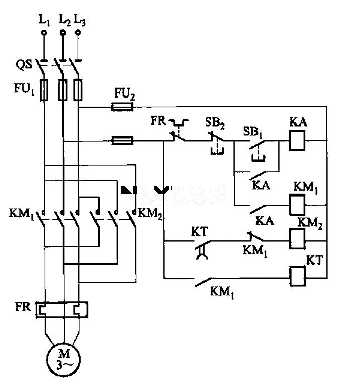
The circuit illustrated in Figure 3-127 utilizes a time relay (KT) in place of a speed relay. The timing duration is adjustable and typically set between 1 to 2 seconds. This circuit is designed to operate effectively in dusty...