
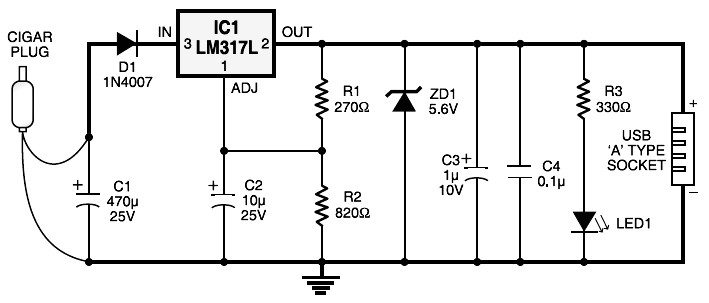
Cigar Lighter Plug to USB Power Socket
The Arduino Uno schematic diagram illustrates a microcontroller board based on the ATmega328. It includes 14 digital input/output pins (of which 6 can be used as PWM outputs), 6 analog inputs, a 16 MHz crystal oscillator, a USB connection, a power jack, and an ICSP. Additionally, there is a simple circuit diagram for a 12V car battery charger. This circuit is designed to prevent battery overcharging, which can lead to electrolyte loss due to evaporation. It monitors the battery's charge condition through a retroactive control circuit by applying a high voltage. This circuit is intended to monitor the power capacity level of a 12V lead-acid battery, with the battery power level indicated by LEDs. This straightforward circuit allows for monitoring the charging process effectively. Final adjustments are simple and require only a digital voltmeter for calibration.
The cigar lighter to USB power socket circuit consists of several key components, including a voltage regulator to step down the 12V input to a stable 5V output. Typically, an LM7805 voltage regulator is employed for this purpose, ensuring that the output remains consistent even with fluctuations in the input voltage. Capacitors may be utilized at the input and output of the regulator to filter out noise and stabilize the voltage levels.
For the USB-powered speaker circuit, the TDA2822M integrated circuit serves as an audio amplifier, providing sufficient power to drive small speakers. The circuit design may include passive components such as resistors and capacitors to set the gain and filter the audio signal, ensuring optimal sound quality. The PCM2706 USB audio controller simplifies the integration of audio capabilities into the circuit, allowing for direct connection to a USB port without the need for additional components or software.
Overall, these circuits exemplify the versatility of USB technology in powering devices and enhancing audio experiences while ensuring safety and efficiency in battery management.Cigar Lighter Plug to USB Power Socket. This circuit is convert 12V DC source from car cigar lighter plug to become USB power sochet with 5V DC output. This circuit can be used to powering 5V electronic devices or recharge the rechargable battery from USB port.
Nowadays, almost all computer systems have logic blocks for working with a USB port. A USB port, in practice, is capable of supplying more than 100 mA of continuous electric current at 5V to the peripherals which are hooked up with the bus. So a USB port could be utilized, without having any problems, for. This is the circuit diagram of USB powered computer speaker, or it widely known as multimedia speakers for PCs.
The circuit has single-chipbased design, low-voltage electrical power supply, compatibility with USB power from computer, simple heat-sinking, inexpensive, large flexibility and wide temperature tolerance. At the heart of the circuit is IC TDA2822M. This IC is, . Here the USB Sound Card circuit based on PCM2706 which dedicated for USB audio. With USB controller module inside PCM2706, there is no more additional programming to the IC. The computer system will automatically detect this circuit when connected tho the USB port. You will get stereo audio channel output from this circuit. Schematic: Components:. Here the Arduino UNO schematic diagram (click to enlarge): About Arduino UNO: The Arduino Uno is really a microcontroller board based on the ATmega328.
It has 14 digital input/output pins (of which 6 may be employed as PWM outputs), 6 analog inputs, a 16 MHz crystal oscillator, a USB connection, a power jack, an ICSP. Here is a simple and easy to build circuit diagram of a 12V car battery charger: The above circuit claimed have ability to prevent battery overcharge that make electrolyte lost due to evaporation.
This circuit will eliminate the problems by monitoring the battery`s condition of charge through its retroactive control circuit by applying a high. This circuit is designed to monitor the level of power capacity at 12V Lead-Acid battery. Battery power level will be indicated by LEDs. This easy circuit makes it possible to monitor the charging process to a higher level. Final adjustsments are simple and easy and the only device required is a digital voltmeter for the. 🔗 External reference
Related Circuits
You need a power supply for a project, but only have a DC adapter available, so you can't use my AC power adapter trick (Project 05). This little project came about because a reader had just this problem, and...
The 230 V, 50 Hz supply is stepped down using a voltage transformer, while a current transformer is utilized to extract the current waveforms. The output of the voltage transformer corresponds to the voltage across the load, and the...
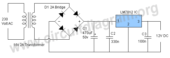
This project involves a straightforward and practical 12V power supply circuit utilizing the LM7812 integrated circuit (IC). The LM7812 is a three-terminal fixed voltage regulator IC housed in a TO-220 package. It incorporates several built-in features such as thermal...
The goals were achieved by utilizing a discrete-components operational amplifier (op-amp) driving a complementary common-emitter output stage configured for Class B operation. In this configuration, for small output currents, the output transistors remain off, allowing the op-amp to supply...
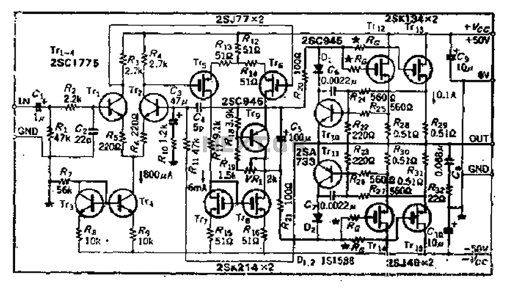
The circuit consists of three identical basic stages, with the second stage featuring a differential output from the power MOSFET, 2SJ77. A current mirror circuit utilizing 2SK214 is implemented. The operating current is 6mA; however, due to the power...
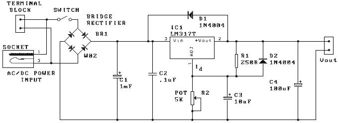
A potentiometer, designated as R2, can be utilized to adjust the desired output voltage. The kit is capable of accepting either AC or DC input through a socket or terminal block. It is advisable to incorporate protection diodes when...
Warning: include(partials/cookie-banner.php): Failed to open stream: Permission denied in /var/www/html/nextgr/view-circuit.php on line 713
Warning: include(): Failed opening 'partials/cookie-banner.php' for inclusion (include_path='.:/usr/share/php') in /var/www/html/nextgr/view-circuit.php on line 713