
High-frequency characteristics are improved power MOSFET amplifier
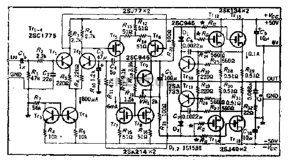
The described circuit is a multi-stage amplifier featuring a differential output stage, which is critical for achieving high fidelity in audio applications or precision in signal processing. The use of the 2SJ77 power MOSFET allows for efficient amplification of the input signal, while the 2SK214 current mirror ensures stable biasing, maintaining consistent operation across varying conditions.
The operating current of 6mA is relatively low, which is advantageous for minimizing power consumption; however, the high supply voltage of 50V poses thermal challenges. The inclusion of a heat sink is essential to prevent thermal runaway and ensure reliable operation over extended periods. The direct drive output stage is particularly beneficial in applications where low output impedance is desired, allowing for better load driving capabilities without the added complexity of an emitter follower buffer.
To address the potential for oscillations, which are common in high-frequency applications, the design incorporates a series gate resistor (Ro) to dampen these effects. The choice of resistance value is crucial; while a lower resistance may enhance high-frequency response, it can also lead to increased susceptibility to oscillation. Therefore, selecting an appropriate value for Ra—considering the specific characteristics of the components used—is vital for maintaining performance integrity.
In summary, the circuit design effectively balances the need for power efficiency, thermal management, and signal integrity, making it suitable for various electronic applications that require robust performance with minimal distortion.And 3 gn same basic circuit, and the second stage is a differential output of the power MOSFET, 2SJ77, a current mirror circuit uses 2SK214. While the operating current is only 6mA, however, because the power supply voltage up to sov, the transistor may have a fever, so install a small heat sink. the output stage chestnut direct drive mode, since without emitter follower buffer, to increase the load driving circuit, and if the need to improve the conversion rate, may try to increase the Tri- * within the range of allowable loss drain on current initiatives.
power MOSFET often have high oscillation, the oscillation to be suppressed relatively sleepy difficult, simple measures are (as close to the gate position) at the gate series resistance ( mark Ro, but want to sacrifice some high frequency characteristics, Ra resistance varies with element member varies, usually between 50Q ~ 500Q.
Related Circuits
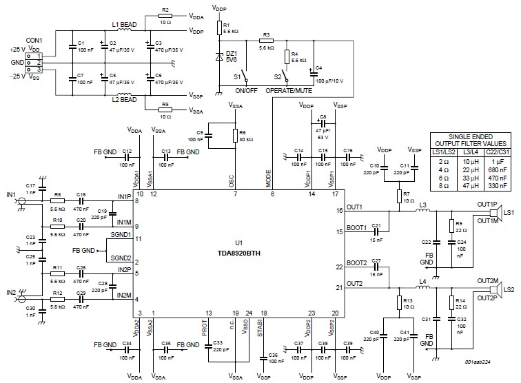
This high-power Class D audio amplifier electronic project is designed using the TDA8920BTH audio power amplifier IC. This power amplifier IC offers very high efficiency with minimal dissipation, yielding significant output power. The typical output power is 200 watts...
The compact 5 pin L165 IC general a stabilized symmetrical power supply from a single asymmetrical power supply. The output voltage is however, half of the input voltage. One needs to add the ripple filter capacitors C1, C2, C3...
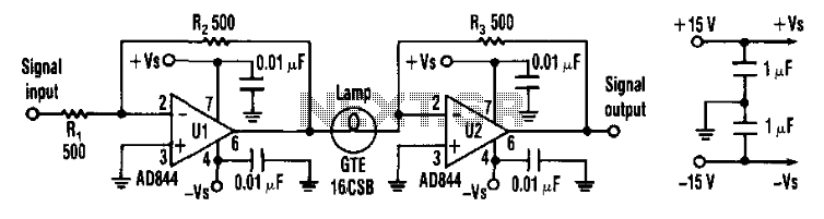
Designers can construct a 15-dB compressor using a miniature lamp and a current-feedback amplifier. The circuit exhibits extremely low distortion at frequencies above the lamp's thermal time constant, indicating that distortion remains negligible from audio frequencies to over 10...
The power failure light that I eventually designed and built is housed in the plastic case from a wall-mounted power transformer. I had accidentally destroyed the transformer by shorting its output, and had kept the plastic case for years,...
The following circuit illustrates a Multi Output Instrument Power Supply Circuit Diagram. Features include the ability to obtain multiple voltage values for cost reduction and basic functionality. The Multi Output Instrument Power Supply Circuit is designed to provide various voltage...
Incorporate a straightforward, economical jack-sensing circuit (JACKSENSE) into a DirectDrive automotive headphone amplifier to detect when headphones are plugged into the audio jack. The implementation of a jack-sensing circuit (JACKSENSE) in a DirectDrive automotive headphone amplifier is designed to enhance...
Warning: include(partials/cookie-banner.php): Failed to open stream: Permission denied in /var/www/html/nextgr/view-circuit.php on line 713
Warning: include(): Failed opening 'partials/cookie-banner.php' for inclusion (include_path='.:/usr/share/php') in /var/www/html/nextgr/view-circuit.php on line 713