
CIRCUIT ALLOWS SLEW RATE CONTROL
The described circuit functions as a slew rate limiter, which is critical in various electronic applications, particularly in servo control systems. The primary objective of this circuit is to restrict the rate of change of the output signal, thereby preventing abrupt changes that could lead to instability in the system.
The circuit typically consists of operational amplifiers (op-amps), resistors, and capacitors configured in such a way that the output signal's rise and fall times are controlled. The op-amps are arranged to compare the input signal with a feedback signal derived from the output. By adjusting the feedback loop, the maximum slew rate can be set for both the positive and negative transitions of the signal independently.
For instance, the positive slew rate can be controlled by a resistor-capacitor (RC) network that determines how quickly the output can rise when the input signal transitions from a low to a high state. Similarly, a separate RC network can be used to control the negative slew rate, allowing for tailored performance based on application requirements.
In practical applications, this circuit is implemented to ensure that the servo system does not exceed the limits of the power supply rails. By limiting the slew rate, the circuit enhances the stability and predictability of the servo response, minimizing overshoot and oscillations that could occur if the system were allowed to respond too quickly to changes in the input signal.
In summary, this circuit serves an essential role in maintaining controlled signal transitions in servo applications, promoting reliable operation within the defined power limits.This circuit (figure 1) will impose a maximum slew rate on a signal; positive and negative rates can be independently controlled. The circuit is useful in servo applications where the error signal needs to be limited to be within the power rails to ensure predictable operation.
🔗 External reference
Related Circuits
The circuit consists of a light metering circuit and a flash circuit, as illustrated in the accompanying image. It is designed for use with integrated cameras such as POPTICS, Franka X-500, and WIZEN-860S. The circuit includes the following components:...
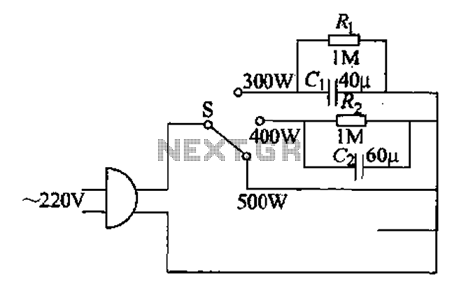
Each family has essential small appliances. The sub-type is an electric power jet, mainly used for clothes and hot shaping. The iron's circuit is shown in Figure 1-30. When using an iron, there is always a concern about using...
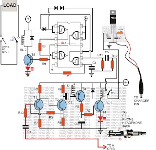
Control any electrical device from anywhere in the world using a cell phone, without incurring costs for individual commands. This system allows operation of various appliances, such as vehicles, doors, and air conditioners, with a simple button press on...
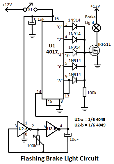
This flashing brake light circuit is designed for motorcycles. When the brake light switch S1 is closed, power is supplied to U1 and U2. The circuit utilizes two inverters from U2. The flashing brake light circuit operates by utilizing a...
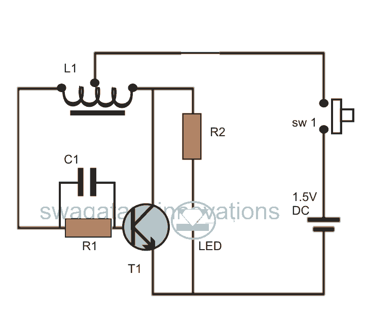
This post discusses blue and white LED drivers utilizing a joule thief circuit. Further exploration of the circuit's functionality is provided, along with simulation points. The joule thief circuit is a simple and efficient boost converter that allows for the...
This class-D audio amplifier is suitable for TV and home stereo systems. The TDA7882 integrated circuit (IC) provides a class-D audio amplifier solution. Since this IC has a single channel output, two units are required for stereo applications. The...