
inner flash circuit of camera
The circuit design integrates a light metering system that utilizes a CdS photoresistor, known for its sensitivity to light levels. The photoresistor's resistance decreases as light intensity increases, providing a variable resistance that is critical for controlling the exposure in the camera. VT1 and VT2 are typically configured as transistors that amplify the signal from the photoresistor, ensuring that even minor changes in light levels can be detected and processed effectively.
The flash circuit, comprising VT3, C1, and T1, is responsible for managing the timing and activation of the flash unit. T1 functions as a transformer that steps up the voltage to trigger the flash, while C1 serves as a capacitor that stores energy, releasing it in a quick burst to produce the flash. The coordination between these components allows for precise control of the flash timing, ensuring that it activates at the optimal moment for capturing images.
Overall, this circuit is designed to enhance the functionality of cameras by providing accurate light measurement and effective flash operation, making it suitable for various camera models and improving the quality of photographs taken in diverse lighting conditions.The circuit is formed by light metering circuit and flash circuit,just as shown in picture.It is suitable for POPTICS (a popular integrated camera), Franka X-500, WIZEN-860S and so on.It consists of the following circuit:(1)VT1,VT2,light metering device RG (using cadmium sulfide CdS photoresistor)form the light metering circuit. VT3,C1,T1 form the indu.. 🔗 External reference
Related Circuits
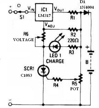
This schematic circuit for a battery charger consists of very few components but operates effectively. When power is applied to the circuit, SCR1 remains off, preventing any bias current from flowing to ground. The LM317 voltage regulator is connected...
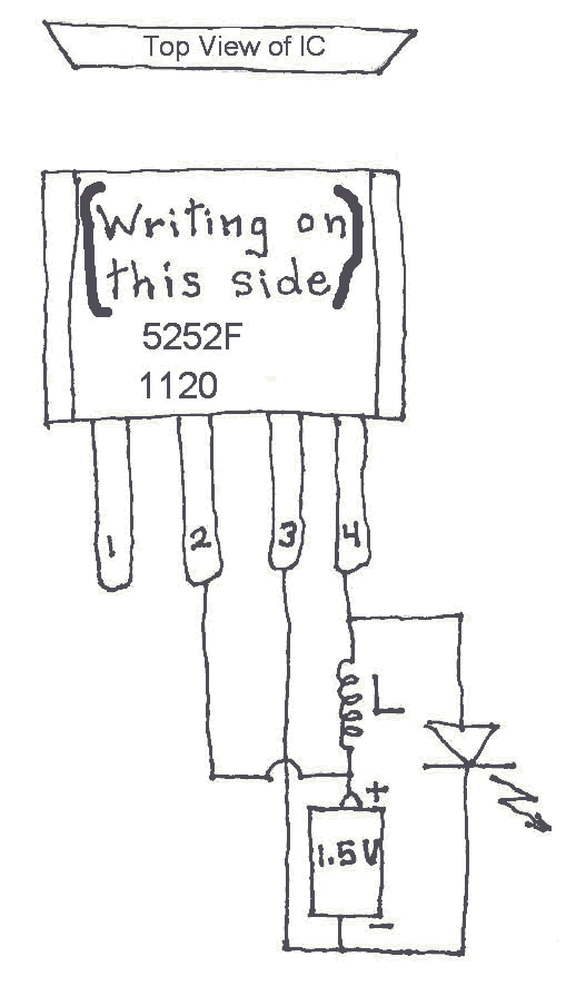
Many Joule Thief circuits traditionally rely on a bulky toroidal inductor that requires careful winding with copper wire. However, there are now compact 4-legged integrated circuits (ICs) available that can perform the same function using only a simple inductor,...
LBl690 is a three-phase brushless DC motor drive control integrated circuit manufactured by Sanyo, a Japanese company. It is extensively utilized in both domestic and imported applications for broken wind and fresh air conditioning systems that require brushless DC drive...
This circuit automatically controls the headlight of a motorcycle, turning it on and off independently of the light and ignition switches, as long as the battery is fully charged. The initial stage employs a 220-ohm resistor and ZD1 to...

Often, there is a need for an additional telephone ringer in an adjoining room to be alerted about incoming calls. For instance, if the telephone is situated in the drawing room, an extra ringer may be required in the...
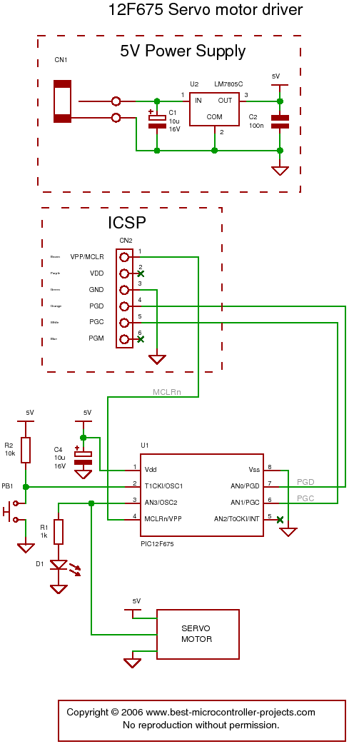
The following circuit illustrates a servo motor driver. This circuit is based on the 12F675 IC. Features include Timer 0 timing and a single control line. The servo motor driver circuit utilizing the 12F675 integrated circuit (IC) is designed to...