
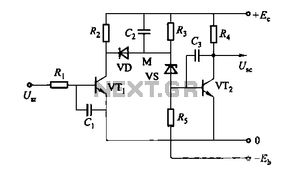
The crystal oscillator circuit with frequency in 2MHz
The two oscillator circuits depicted in the figures utilize different configurations to achieve stable oscillation at the desired frequency of 2 MHz. The first circuit may employ a Colpitts or Hartley oscillator design, which is characterized by its use of capacitive and inductive components to establish feedback for oscillation. The second circuit might utilize a phase-shift oscillator configuration, relying on resistive and capacitive elements to create the necessary phase shift for sustained oscillation.
Both circuits incorporate a transistor or operational amplifier as the active component, which amplifies the feedback signal to maintain oscillation. The tuning elements, typically variable capacitors or inductors, facilitate fine-tuning of the frequency to ensure precision at 2 MHz. Testing and adjustment of these components are crucial for achieving the best operating point, as variations in component values can significantly affect the frequency stability and amplitude of the output signal.
Power supply considerations should also be addressed, ensuring that the circuits are powered adequately to prevent distortion or signal degradation. Additionally, output coupling may be implemented to interface with other stages of a system, which could include filtering or impedance matching networks to optimize signal integrity and minimize losses.
In conclusion, the ability to adjust the operating point through testing is essential for maximizing the performance of these oscillator circuits, making them suitable for various applications in signal generation and modulation.Figure (a) and (b) show the two 2MHZ basic oscillator circuits. According to the circuit structure, it can adjust its best operating point by testing.. 🔗 External reference
Related Circuits
The discharge process in the memory circuit is an instantaneous action, followed by a delay reset circuit. When the input signal is activated, the circuit opens. Once the input signal is removed, the circuit begins counting after a predetermined...
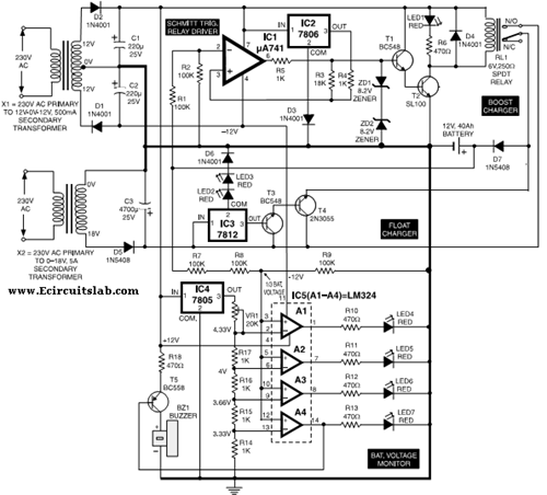
This circuit illustrates the use of the 7806 IC in an automatic battery charger circuit diagram. It is designed for a car battery with an approximate rating of 40 Ah. The automatic battery charger circuit utilizing the 7806 integrated circuit...
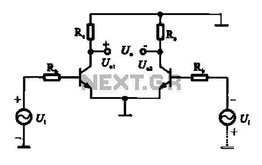
An amplifier circuit is designed to handle an assumed input consisting of two equal and opposite polarity signals, known as a differential mode signal. The two tube collector currents, Ic and IC7, are balanced in such a way that...
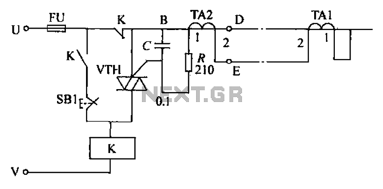
The circuit's current exceeds the load carried by the rated current meter, prompting the user to immediately cut off the power supply to address the overload. Pressing the reset button restores power, making the system simple, convenient, and practical....
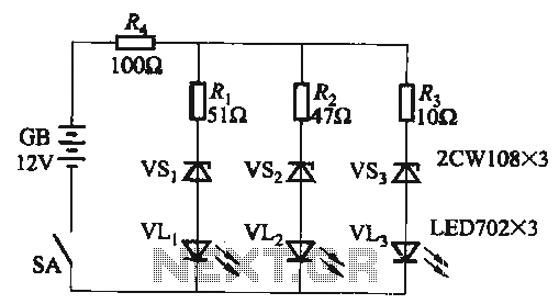
When the supply voltage falls below 10.2V, the yellow light-emitting diode (LED) VLi illuminates, indicating that the storage pool can no longer continue to discharge. Additionally, when the voltage exceeds 16.2V, the yellow, green, and red light-emitting diodes (LEDs)...
The ZN414 is an economical, single-chip AM radio integrated circuit introduced in 1972 by Ferranti. The TDA7000 is a monolithic integrated circuit designed for mono FM portable radios or receivers, focusing on minimizing size. Additionally, there is an FM...