
Circuit diagram for basic alarm with delayed trigger
The CD4001 quad 2-input NOR gate is a fundamental building block in digital electronics, offering flexibility in design and application. In this alarm system, the gates are configured to create a logic circuit that can manage both the triggering and deactivation of the alarm. The integration of R1 and C1 provides a time delay that is critical for user interaction, allowing the user to enter a code or perform necessary actions without immediate triggering of the alarm. The choice of resistor and capacitor values directly influences the performance of the delay mechanism, enabling customization based on specific user requirements or system constraints.
The addition of the automatic turn-off feature is particularly beneficial in scenarios where manual intervention may be impractical. By utilizing C2 and R2, the system ensures that the alarm will not remain active indefinitely, thus conserving power and preventing unnecessary disturbances. The careful selection of component values for these delay circuits allows for a wide range of operational durations, making the system adaptable to various environments and security needs.
The use of diodes in the circuit, such as the 1N4148, plays a crucial role in maintaining the integrity of the logic levels and ensuring that the alarm system operates reliably. The diode's ability to prevent backflow of current protects sensitive components and stabilizes the circuit during operation. Overall, the design exemplifies the effective use of the CD4001 NOR gate in creating a practical and efficient alarm system, showcasing the versatility and functionality of this integrated circuit in real-world applications.The CD4001 quad 2-input NOR gate is a very versatile IC that can be used in an almost infinite variation. Here we will use it in the application of a simple alarm system. The power supply suggested for the CD4001 is 5 to 15Vdc Max. The CD4001 has a typical transition voltage value of 50% of its supply voltage with a possible spread of 30% to 70% d
epending on its production. The delay is set by R1/C1) for exemple, R1=680k and C1=10uf give a time delay of approx 8 secs. Thus time can adjusted by the choice of R/C values. This delayed trigger allows time to set the module in the "Standby" and exit within the time delay period before the alarm is triggered. Again on re-entering the alarm must be reset within that delay period. Gate A forms the trigger circuit and gates B&C form a tone generator of 800hz to the speaker activated by the transistor.
In the next circuit in addition to the delay ON circuit we added an extra gate to provide for an auto/delayed turn off function. C2 & R2 are used to automatically turn off the alarm. Like C1 & R1, C2 & R2 can be selected for the duration the alarm will stay on then automatically turned off.
It must be reset to be reactivated. Two outputs are available as shown. But, the delay period may not be long enought to manually reset the unit. We can eliminate the guess work by integrating an auto-exit /entry delay that will not require a manual reset as shown in the next circuit. R1/C1 and R2/C2 forms the exit /entry delay ciruits. When the power is first applied (standby) all sensor switches (S3, S4) are enabled except S1a/b which is disabled for a pre-set period via time-delay network C1/R1.
At the end of this period S1 is automatically enabled. When S1 is activated the output of gate-A goes high and is locked by the action of D1 diode(1N4148) and gate-D. This high output voltage is applied to the input of gate-B via C2/R2 delay network an after a pre-set delay the voltage reaching gate-B rises to such a value that the alarm is activated.
🔗 External reference
Related Circuits
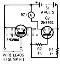
A common collector amplifier drives a 2N3904 switch to sound alarm BZ1. The wire leads to a water sensor or sump pit, level switch, etc. It is used to allow the alarm to operate and be mounted in a...
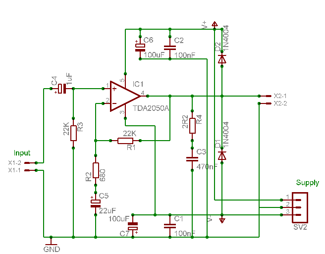
A careful examination of the amplifier photos reveals that the heatsink on the HY60 near-clone built using the TDA2050A is slightly shorter than that of the original HY60s. This unit is positioned at the rear of the amplifier, creating...
A capacitance meter is an essential instrument for electronics hobbyists and professional electronic technicians. A capacitance meter is a specialized device used to measure the capacitance of capacitors in electronic circuits. It is a valuable tool for diagnosing and troubleshooting...
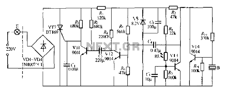
A modified piezoelectric ceramic acoustic-electric transducer is utilized to create a sound and light control system for a stairway walkway with a delay lighting switch. The circuit structure is relatively simple, consisting of diodes VD1 to VD4 and a...
DC Motor Control Using a Single Switch. This simple circuit allows for the operation of a DC motor in both clockwise and counterclockwise directions, as well as stopping it using a single switch. The circuit utilizes non-latching push button...
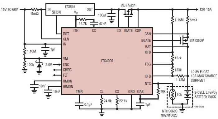
The LTC4000 high voltage controller, developed by Linear Technology, can be utilized to create a straightforward high current LiFePO4 battery charger. This charger delivers a fixed output voltage of 12 volts with a maximum output current of 15 A....
Warning: include(partials/cookie-banner.php): Failed to open stream: Permission denied in /var/www/html/nextgr/view-circuit.php on line 713
Warning: include(): Failed opening 'partials/cookie-banner.php' for inclusion (include_path='.:/usr/share/php') in /var/www/html/nextgr/view-circuit.php on line 713