
Simple Flood Alarm Circuit
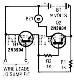
The circuit utilizes a common collector amplifier configuration, which is also known as an emitter follower. This setup is characterized by its ability to provide high input impedance and low output impedance, making it suitable for interfacing with various sensors. In this specific application, the 2N3904 transistor serves as a switch that is activated by the output of the common collector amplifier.
The alarm system includes an audible alert, represented by the BZ1 component, which is typically a piezo buzzer or similar device. When the water sensor detects a specific level of water in the sump pit or other monitored area, it sends a signal to the common collector amplifier. This amplifier increases the current to a level sufficient to turn on the 2N3904 transistor. Once activated, the transistor allows current to flow from the power supply through the BZ1 alarm, thereby sounding the alert.
The design emphasizes the need for the alarm system to be mounted in a dry location, which is crucial for the longevity and reliability of the components involved. Proper insulation and housing for the circuit can prevent moisture-related issues that could lead to false alarms or circuit failure. The wiring from the water sensor or level switch to the amplifier must be carefully routed to avoid exposure to water, ensuring that the circuit operates effectively under various environmental conditions.
Overall, this common collector amplifier circuit provides a reliable method for monitoring water levels and activating an alarm system, making it an essential component in applications such as sump pumps, flood detection systems, and other water management solutions. A common collector amplifier drives a 2N3904 switch to sound alarm BZ1. The wire leads to water sensor or sump pit, level switch, etc. and used to allow the alarm to operate and be mounted in a dry place. 🔗 External reference
Related Circuits
The alarm detector circuit operates differently from the Ultrasonic Alarm (1). In Ultrasonic Alarm (1), an alarm output is triggered by the detection of a reflected wave from an object during the setup time. Conversely, in this circuit, an...

This unit captures the ATV signal by sampling the transmission line with minimal insertion loss. It features two N connectors for input and output connections, and a BNC connector is utilized for the video output. The detected output is...

The microphone input, MIC1, is connected through capacitor C3 and resistor R4 to the inverting amplifier U2-a, where the gain of U2-a is adjusted by potentiometer R5. The output from U2-a is passed through capacitor C4 to the remaining...
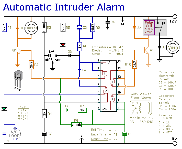
This is a simple single-zone burglar alarm circuit. Its features include automatic Exit and Entry delays and a timed Bell/Siren Cut-Off. It is designed to be used with the usual types of normally-closed input devices such as magnetic reed...
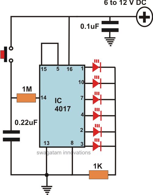
This article offers a circuit diagram and a discussion on CMOS logic and IC layout for creating a set of attention-getting LED running lights. It details a simple sequential LED flasher or light chaser that can be built, including...
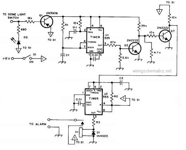
This circuit diagram represents a smart car alarm timer. This design is more advanced compared to traditional car alarm systems. When activated, the alarm remains active for 80 seconds, following an initial delay of 15 seconds. The smart car alarm...
Warning: include(partials/cookie-banner.php): Failed to open stream: Permission denied in /var/www/html/nextgr/view-circuit.php on line 713
Warning: include(): Failed opening 'partials/cookie-banner.php' for inclusion (include_path='.:/usr/share/php') in /var/www/html/nextgr/view-circuit.php on line 713