
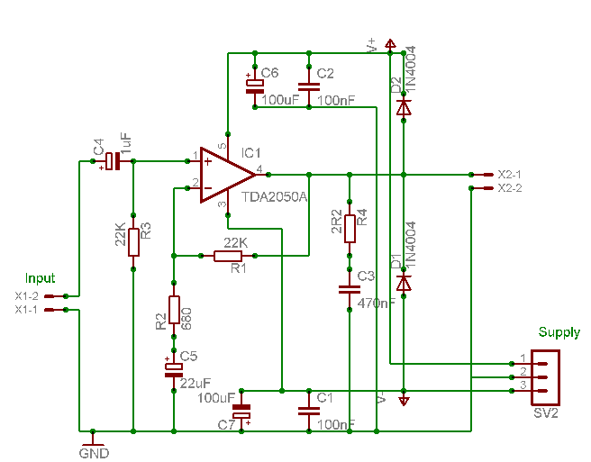
3-channel Audio Amplifier circuit
Safety is paramount when dealing with mains voltages. Each brass panel is connected with sturdy insulated wire to the brass panel on the power supply unit (PSU), to which the Earth from the mains supply is connected. This connection is made via a 100-ohm resistor to the 0V line of the PSU. Additionally, a similar wire connects the transformer pan base to Earth. For the 0V line on the PSU, a small-diameter brass bar is utilized, allowing connections from the amplifier at any point in a 360-degree orientation. The positive and negative connections are made using reasonably heavy (10 amp) insulated wire. Notably, a change of mind resulted in cross-connecting colors on the capacitors, leading to a RED negative wire and a BLUE positive wire—this is not advisable for others to replicate. To avoid a larger case, two sets of three 6800uF capacitors were used in place of two 20,000uF capacitors, with receptacles drilled in the base slab using a Forstner bit. The bridge rectifier is secured to one of the small brass panels with a bit of silicone grease to assist in cooling. The transformer pan cut-out is made slightly larger than the transformer itself to allow for air circulation around the periphery, facilitated by holes drilled in the pan base. The transformer, purchased from RS Components, did not come with a fitting kit, which was assumed to be included. As a solution, bottom and top gaskets were improvised from a silicone heat mat, and the top fixing plate was crafted from 22-gauge aluminum.
The described amplifier circuit incorporates a TDA2050A audio amplifier IC, which is known for its ability to deliver high-quality audio output while maintaining thermal efficiency. The heatsink, although shorter than the original design, is strategically placed to promote airflow, enhancing the overall thermal management of the amplifier. The choice of materials, such as brass for the panels and aluminum for the fixing plate, contributes to both the durability and aesthetic of the unit.
The power supply section is designed with safety as a primary concern, employing insulated wiring and a resistor to ensure proper grounding. The use of a small-diameter brass bar for the 0V line facilitates versatile connections, allowing for ease of assembly and maintenance. The decision to utilize multiple smaller capacitors instead of fewer larger ones reflects a practical approach to space management within the amplifier casing while still achieving the desired capacitance for stable power delivery.
The bridge rectifier's mounting with silicone grease indicates a focus on thermal dissipation, which is critical in preventing overheating during operation. The transformer pan's design, featuring a larger cut-out for airflow, further emphasizes the importance of thermal management within the circuit. Overall, these design choices reflect a thorough understanding of electronic principles while ensuring the functionality and safety of the amplifier circuit.Careful examination of the photos of the amplifier will reveal that the heatsink on the HY60 near-clone I built using the TDA2050A is slightly shorter than that on the original HY60s. I placed this unit at the rear of the amplifier, and the gap provides adequate space for a free-flow of air up the inside of the amplifier.
No slots were cut in the bottom-side of the top slab, this is lined up and held firmly in place with three large woodscrews driven through the middle-tier upwards. Safety should be paramount where mains voltages are concerned, and each Brass panel is connected with stoutish insulated wire to the brass panel on the PSU to which the Earth from the mains supply is connected. This was then connected via a 100 ohm resistor to the 0v line of the PSU. A similar wire connected to the transformer pan base is also connected to Earth. For the 0v line on the PSU I used a small-diameter brass bar, which allows connections from the amplifier at any point in 360 degs.
The +ve and -ve connections were done using reasonably heavy (10 amp) insulated wire. Look carefully at my photos of the PSU and you will see that a change of mind resulted in me cross-connecting colours on the capacitors, so that I ended up with a RED -ve wire and a BLUE +ve wire – don’t do this at home! To have fitted two 20,000uF capacitors would have resulted in a larger case, so I substituted these for two sets of 3 X 6800uF, and sited these by drilling receptacles in the base slab using a Forstner bit.
The bridge rectifier is fastened to one of the small Brass panels using a little silicone grease to aid cooling. Note that I made the transformer pan cut-out slightly larger than the Tx itself, to allow for the free flow of air around the periphery, via holes drilled in the pan base.
The transformer (which I bought from RS components) came without a fitting kit (I had assumed this was included). I improvised bottom and top gaskets cut from a cheap silcone heat mat, and the top fixing plate from 22 gauge Aluminium.
🔗 External reference
Related Circuits
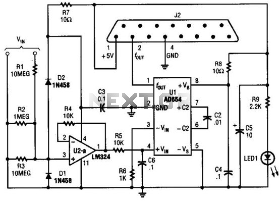
The adapter comprises a voltage-to-frequency converter integrated with a signal conditioning and protection circuit. J2 interfaces with the game port of a personal computer. Additional software references are available for use with this circuit. The voltage-to-frequency adapter functions by converting...

A digital amplifier is a new device that IC manufacturers are eager to capitalize on, leading to the launch of unique digital amplifier products. Below are brief descriptions of some representative devices. The TA2022, produced by Tripath, is an...
The total gain of the car antenna amplifier is approximately 30 dB, with an input impedance of around 10 kΩ at 30 MHz. The amplifier should be mounted directly at the base of the antenna to prevent signal losses...
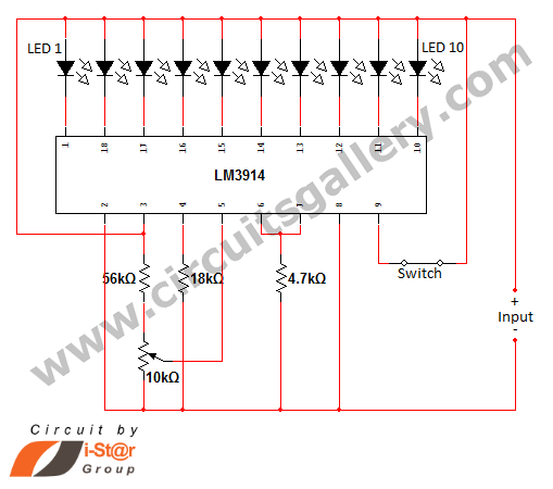
In various situations, it is necessary to indicate the amount of battery charge using methods such as LED dot displays or LED bar displays. This circuit utilizes the LM3914 integrated circuit to serve as a battery charge indicator with...
Diagram 2 depicts a shake tube circuit with a capacitance (C) and a trigger voltage rectifier filter element. The circuit includes a trigger voltage transistor amplifier (H), three pull tubes (n, U, v), and utilizes a thyristor as a...

In this circuit we use the 2SK1058 and the 2SJ162 Mosfets. This could be avoided by a fairly simple bootstrapping circuit, but the improvement in maximum output may be just a fraction of a dB, depending on the supply...
Warning: include(partials/cookie-banner.php): Failed to open stream: Permission denied in /var/www/html/nextgr/view-circuit.php on line 713
Warning: include(): Failed opening 'partials/cookie-banner.php' for inclusion (include_path='.:/usr/share/php') in /var/www/html/nextgr/view-circuit.php on line 713