
Circuit diagram of an analog circuit PWM
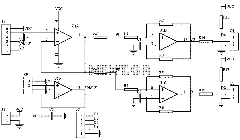
The circuit utilizes a linear potentiometer or Hall effect sensor to generate control signals for the PWM (Pulse Width Modulation) used in driving two motors. The potentiometer is positioned to allow for dual-axis control, enabling precise manipulation of the model aircraft's movement. The circuit's design incorporates operational amplifiers U1A and U1B to manage voltage levels effectively; U1B stabilizes the voltage to half the supply level, which is critical for accurate motor control.
The synthesized signals derived from the potentiometer's x and y readings are mathematically processed to yield the desired motor speed control voltages. The equations employed for this purpose allow for dynamic adjustments based on user input, ensuring that the aircraft responds accurately to joystick movements. The Schmitt oscillator configuration formed by U1C and U1D is essential in translating the varying voltage levels into a stable PWM signal, which is crucial for motor control applications.
Hysteresis, created by resistors R1 and R2, helps to prevent noise from causing erratic behavior in the output signals. This feature is particularly important in environments where electrical noise may interfere with the control signals. The timing components, C1 and R3, work together to define the frequency and duty cycle of the PWM signal, allowing for fine-tuning of the motor speed.
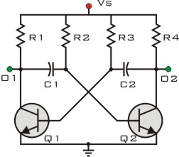
Transistors Q1 and Q2 serve as inverters, ensuring that the control signals are appropriately processed to drive the motors effectively. The circuit design reflects principles found in classic oscillator circuits, such as the 555 timer, emphasizing the importance of stability and reliability in electronic control systems. This configuration is well-suited for applications requiring precise control of motor functions, such as in remote-controlled model aircraft.The picture shows the use of a linear potentiometer (or linear Hall element) control two chassis drive motor PWM generation circuit gamepad or joystick on the model aircraft. J1 is the handle of the socket 123 and 456, respectively potentiometer x, y in both directions. U1B provides half supply voltage, U1A is a voltage follower. x, y component of the left and right wheels via synthetic become two motor speed control voltage signal. In use, let L = (x + 1) y / (x + 1.4), R = (x-1) y / (x-0.6), tested have good results (digital units only, not the voltage value) .
After U1C and U1D Schmitt oscillator consisting of a voltage converted to the corresponding PWM signal for controlling power driver circuit. In Case U1D, R1, R2 have the composition hysteresis Schmitt trigger circuit, that the upper and lower threshold of input voltage, C1 and R3 delay circuit, thus formed by the oscillation width input voltage control.
Q1, Q2 is a transistor, the composition of the inverter provides the control signal difference. Analysis of the oscillator 555 on textbooks refer to the specific oscillation digital circuits.
Related Circuits
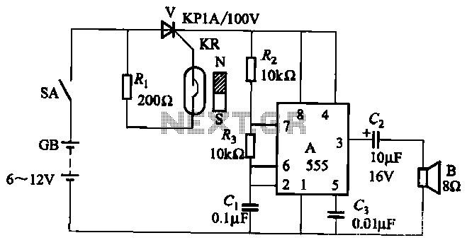
The circuit utilizes a reed switch KR with a control thyristor V for conduction, along with a 555 integrated circuit configured as a multivibrator to function as an alarm generator. When the door is closed, a permanent magnet is...
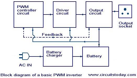
Nowadays, most inverters available in the market utilize Pulse Width Modulation (PWM) technology. Inverters based on PWM technology exhibit superior performance in several aspects compared to those designed using conventional methods. These PWM inverters typically employ MOSFETs in the...
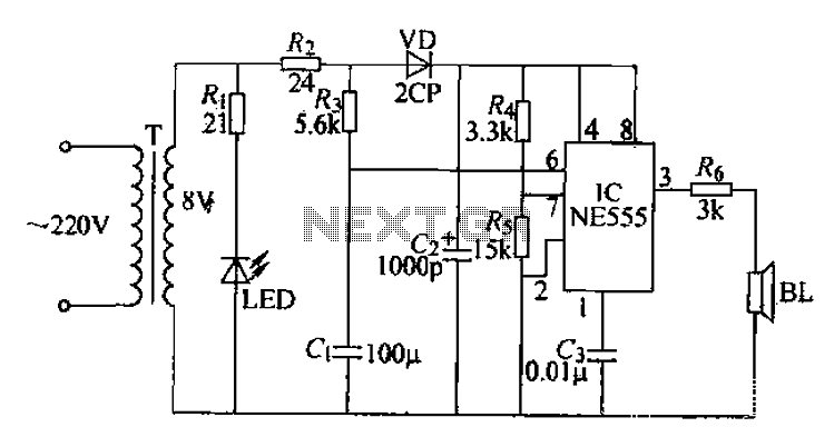
Electrical pulses are generated by the output of the first base circuit pin and sent through the R6 piezoelectric speaker, which converts the electrical pulses into ultrasonic waves. The circuit operates on a simple sweep principle, utilizing the transformer’s...
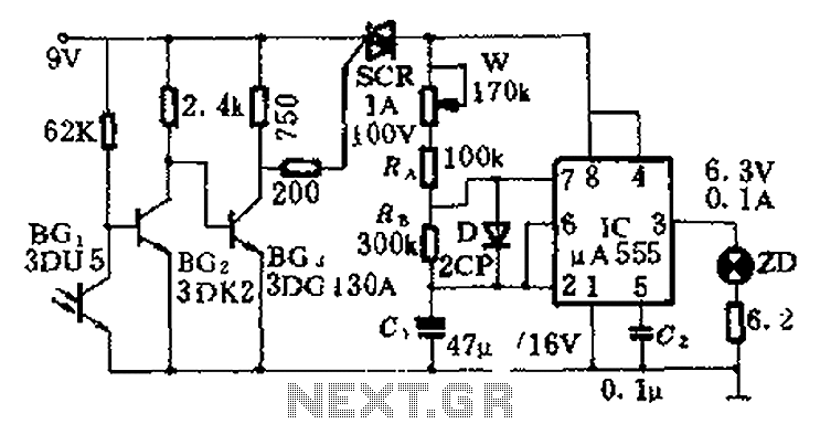
This circuit is designed for nighttime illumination and corridor lighting. During daylight, sufficient light causes BG3 to conduct, preventing the SCR from oscillating. As a result, the circuit remains inactive, and the light does not turn on. At night,...

This design outlines a sensor circuit that utilizes an LED as a light sensor. The operational control and amplification of the output are managed by a 1458 integrated circuit (IC), which functions as an operational amplifier (op-amp). The circuit...
This circuit is designed to drive a relay coil using a low power output, typically from an integrated circuit (IC) such as a 555 timer or a TTL/CMOS device. It facilitates the switching of high loads or loads requiring...
Warning: include(partials/cookie-banner.php): Failed to open stream: Permission denied in /var/www/html/nextgr/view-circuit.php on line 713
Warning: include(): Failed opening 'partials/cookie-banner.php' for inclusion (include_path='.:/usr/share/php') in /var/www/html/nextgr/view-circuit.php on line 713