
led photo sensor circuit

The sensor circuit operates by leveraging the unique properties of an LED, which can generate a small voltage when exposed to light. This photovoltaic effect is harnessed to detect varying light levels. The JFET serves as a buffer, isolating the LED from the op-amp input to prevent loading effects that could distort the signal.
The 1458 op-amp amplifies the buffered voltage signal, effectively increasing its magnitude to a more usable level. The gain of the op-amp is set to approximately 20, which means that for every 1 volt change at the input, there will be a corresponding 20 volts change at the output. This gain is crucial for applications where significant voltage swings are necessary to trigger subsequent electronic components or systems.
The inclusion of a 100K potentiometer allows for fine-tuning of the output voltage. In complete darkness, the output can be adjusted to reach around 7 volts, providing a clear indication of low light conditions. As ambient light increases, the output voltage drops, reaching about 2 volts in bright light. This range of output voltages can be utilized to interface with other circuits, such as microcontrollers, for further processing or control actions.
Overall, this sensor circuit design provides a robust solution for light detection applications, combining simple components to achieve effective light sensing capabilities with adjustable output levels.This is a design for sensor circuit. This circuit is using LED for sensor a light. But, for control operation and amplifier the output is using 1458 IC. This is an op-amp. This is the figure of the circuit; A circuit that is takes advantage of the photo-voltaic voltage of an ordinary LED. The LED voltage is buffered by a junction FET transistor an d then applied to the inverting input of an op-amp with a gain of about 20. This produces a change of about 5 volts at the output from darkness to bright light. The 100K potentiometer can be set so that the output is around 7 volts in darkness and falls to about 2 volts in bright light. 🔗 External reference
Related Circuits
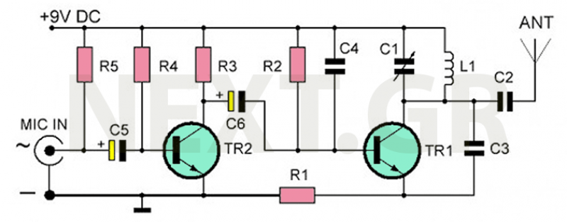
The recommended transmitter is straightforward to construct and suitable for beginners. Despite its simple design and compact size, it delivers remarkable performance. It operates for 12-15 hours on a 9-volt battery and has a transmission range of 100 to...

This is a simple game circuit designed for multiplayer enjoyment. The objective is to score one hundred points within a limited timeframe. To restart the game, the S1 button switch must be pressed. It is important to ensure that...

The circuit depicted in Figure 3-162 includes several components: SBi serves as the forward start button, SBz functions as the reverse start button, and SB3 is designated as the stop button. The resistance levels for the start switches are...

The output displays a 5V / 0.4A low-power switching power supply circuit, which can be utilized to create a transformer saturation soft-switching circuit. This low-power switching power supply circuit is designed to provide a stable 5V output at a current...

Although LEDs dominate the lighting market today, a standard flashlight bulb can still be a viable light-emitting option, particularly due to its simpler configuration compared to an LED. When the AC mains supply fails, transistor T1 becomes forward-biased, allowing...

UART, GPS. This application note illustrates how to integrate a GPS module SC16C2552B into a navigation system using a Philips UART. With the rapid advancement of GPS (Global Positioning System) technologies, GPS is being increasingly utilized across various sectors....