
circuit explanation of stepper motor

The Darlington transistor configuration is particularly advantageous in applications requiring high current gain and fast switching capabilities. The series connection of two transistors allows for the amplification of input signals, making it suitable for driving inductive loads such as coils in motors. The use of the 2SD1209K transistor with an hfe of over 4000 ensures that even small input currents can effectively drive larger output currents, which is essential for applications involving motor control.
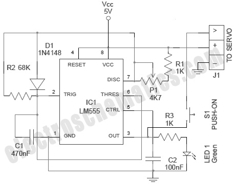
In the described circuit, the integration of the capacitor C1 plays a crucial role in controlling the timing of the motor operation. The charging and discharging characteristics of the capacitor can be manipulated by adjusting the resistor values, specifically VR1. This flexibility allows for precise control over the motor's speed and responsiveness, which is vital in applications requiring accurate positioning or speed modulation.
The protection diode serves a critical function by safeguarding the transistor against back EMF generated by the motor coil during switching events. This back EMF can cause voltage spikes that may exceed the transistor's maximum ratings, potentially leading to failure. By ensuring that the diode conducts during these events, the circuit maintains reliability and longevity.
The choice of a non-locking pushbutton switch adds to the user-friendliness of the circuit, allowing for simple control of the motor's operation without the need for complex mechanical latching mechanisms. The inclusion of external pull-up resistors is a common practice in digital circuits to ensure that inputs are not left floating, which could lead to unpredictable behavior.
Overall, this circuit design exemplifies efficient motor control through the careful selection of components and configuration, allowing for versatile operation in various applications. The integration of a microcontroller such as the PIC16F84A enhances the circuit's capabilities by enabling programmable control, further expanding its potential uses in automated systems.Darlington connection-type transistor is used for the drive of the coil. As for the Darlington connection, 2 stages of transistors are connected inside in series. The "hfe" of this transistor is the multiplication of the "hfe" of each transistor inside. In case of 2SD1209K which was used this time, the hfe is over 4000. Because the ratio of the in put electric current and the output current is big, the rising edge and the falling edge of the control signal can be made sharp. The diode to be putting between the collector and the power is for the protection of the transistor. When the transistor becomes OFF from ON, the coil of the motor tries to continue to pass an electric current and generates high voltage.
An electric current by this voltage is applied to the diode and the high voltage which applies over the transistor is prevented. TR1 becomes ON condition when RB7 becomes H level. In this condition, the electric charge of capacitor C1 flows through the transistor and the voltage of the both edges of the capacitor becomes 0 V almost.
When RB7 becomes an L level, the transistor becomes OFF condition. In this condition, the electric current flows through VR1 and R4 into capacitor C1 and the charging to the capacitor begins. The voltage of the both edges of the capacitor becomes high gradually as charging is done. As for the change of this voltage, refer to "Integration circuit". The voltage of the capacitor is detected by RB5. The software of PIC interrupts the control of the motor until it checks RB5 after making RB7 an L level and RB5 becomes H level.
When making the value of VR1 small, the charging time of the capacitor is short and the control of the motor becomes quick. The control of the motor becomes slow when making VR1 big. The speed control range can be changed by changing the value of the capacitor. This is the circuit for the clockwise rotating, the counterclockwise rotating or stopping a motor. The baton switch of the non lock is used. Pull-up resistor is used for the port to become H level when the switch is OFF. The RB port of PIC16F84A has an internal pull up feature. However, because RB5 is used for the voltage detection of the capacitor at the circuit this time, an internal pull up feature isnt used.
If using RA port for the voltage detection of the capacitor, the RB internal pull up feature can be used. The circuit this time put an external pull-up resistor in the relation of the pattern. Because the operating voltage of the stepper motor to be using this time is about 5V, the power supply voltage is +5V.
In this case, the voltage which is applied to PIC becomes less than 5V because of the voltage drop (about 1V) of the regulator. In case of PIC16F84A, the operation is possible even if the power falls to about 3V because the operating voltage range is from 2V to 5.
5V. It is enough in the 100-mA type. 🔗 External reference
Related Circuits
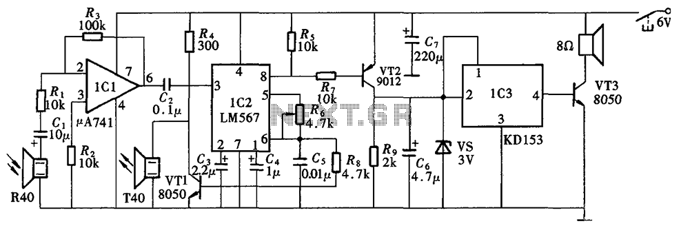
The Blind Pathfinder circuit primarily consists of the A741 operational amplifier, LM567 phase-locked loop, KD153 transistor, 8050 transistor, 9012 transistor, and various other components. The Blind Pathfinder circuit is designed to assist in navigation and obstacle detection, typically utilized in...
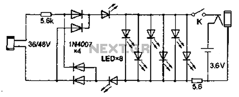
Also known as the Free lamp (commonly referred to as the Myanmar lamp by online sellers), this device operates using the voltage from a standard household fixed telephone line, eliminating the need for batteries or AC power. The lamp...
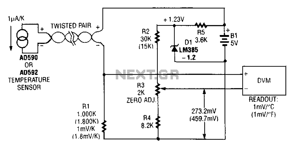
An AD590 or AD592 can be utilized in a transmission line for temperature data transmission. The circuit generates a value of 1 mV per degree Fahrenheit. The AD590 and AD592 are precision temperature sensors that output a voltage proportional to...
In this circuit, a simple calculator, in conjunction with a COB (chip-on-board) from an analogue quartz clock, is used to make a telephone call meter. The calculator enables conversion of STD/ISD calls to local call equivalents and always displays...
A servo is an error-sensing feedback control mechanism used to correct the performance of a system. A servo motor is a DC motor equipped with a servo mechanism. A servo motor is an electromechanical device that utilizes a closed-loop control...
The cooling is not only a PC using a small fan with an electronic commutator. A special feature of these fans is that their removal is less dependent on the load. Indicators monitoring the DC component of current may...