
Blind Pathfinder circuit diagram
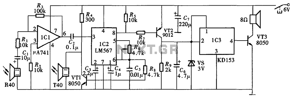
The Blind Pathfinder circuit is designed to assist in navigation and obstacle detection, typically utilized in robotic applications. The A741 operational amplifier serves as a key component for signal amplification, allowing for the processing of weak signals received from sensors. The LM567 phase-locked loop is employed for frequency detection, enabling the circuit to determine the presence of specific signals related to navigation.
Transistors such as the KD153, 8050, and 9012 are integrated into the circuit for switching and amplification purposes. The KD153, being a general-purpose NPN transistor, can handle moderate power levels, making it suitable for driving loads within the circuit. The 8050 and 9012 transistors are utilized for their switching capabilities, allowing the circuit to control various outputs based on the processed sensor signals.
Additional components may include resistors, capacitors, and diodes, which are essential for biasing, filtering, and protecting the circuit. Proper configuration of these components is crucial for ensuring the stability and performance of the Blind Pathfinder circuit.
In summary, the Blind Pathfinder circuit integrates various electronic components to facilitate effective navigation and obstacle avoidance, making it an essential tool in the field of robotics and automated systems. Blind Pathfinder circuit is mainly composed of A741, LM567, KD153, 8050, 9012 and other components.
Related Circuits
This project utilizes an LM338 adjustable three-terminal regulator to deliver a current of up to 5A with a variable output voltage ranging from 2V to 25V DC. It is particularly useful for powering various electronic circuits during the assembly...
This preamplifier is designed to interface with CD players, tuners, tape recorders, and similar devices, providing an AC voltage gain of 4 to drive less sensitive power amplifiers. Given that modern Hi-Fi home equipment often comes with small loudspeaker...

This is a simple preamplifier circuit designed for an electret condenser microphone, utilizing an LM1458 dual op-amp integrated circuit (IC). The circuit amplifies the audio signal from the condenser microphone, allowing it to be used as an input for...

The TOP100Y is a flyback DC switching power supply circuit with a +5V, 1A output. This power supply features a feedback circuit that directly regulates the output voltage, making it suitable for applications that require electrical isolation and minimal...

The circuit illustrated in the figure represents a specialized power supply configuration. It is straightforward in design and can be constructed using two identical secondary windings to generate three distinct DC voltage outputs: +5V, -5V, and +12V. The circuit...

A series of LEDs is used to alert the gardener when plants require watering. By utilizing two conventional digital integrated LEDs along with a series of additional LEDs, this device serves as a practical tool for gardening. It detects...