
Circuit of RIIA phono pre-amplifier op-27
The described circuit is a sophisticated audio processing unit designed to ensure high fidelity and minimal noise interference. The low voltage and current noise specifications indicate a high level of precision in component selection and circuit design. The choice of 100-ohm resistor R3 effectively reduces additional noise, demonstrating a thoughtful approach to noise management.
The RIAA network formed by resistors R1, R2 and capacitors C1 and C@ is crucial for maintaining the accuracy of audio signal reproduction. The specified time constants of 3180 µs, 318 µs, and 75 µs are indicative of the circuit's ability to accurately process audio signals across a wide frequency range, ensuring that the bass, midrange, and treble frequencies are reproduced correctly.
The use of metal-film resistors and film capacitors made from polystyrene or polypropylene is a critical design choice that enhances the circuit's stability and equalization characteristics. These components are known for their low noise and high stability, which contribute to the overall performance of the circuit.
The filter created by capacitor C3 and resistor R4 is designed to attenuate frequencies above 22 Hz, effectively reducing unwanted low-frequency noise and ensuring that the audio signal remains clear and defined. The -6 dB/octave slope indicates a gradual roll-off, minimizing phase distortion and maintaining the integrity of the audio signal.
The circuit's performance is impressive, with distortion levels below 0.01% at the input and less than 0.03% at the output when operating at 3V and frequencies above 20 kHz. This low distortion is essential for high-quality audio applications, making the circuit suitable for professional audio equipment where clarity and fidelity are paramount. Overall, the design reflects a comprehensive understanding of audio electronics, optimizing both performance and reliability.He only contributes with 3. 2nV/ HZ of noise tension and 0. 45pA/ HZ of current noise to the circuit. To minimize the noise of other sources, R3 it is configured for 100 ©. That generates tension of noise additional of only 1. 3nV/ HZ. R1, R2, c1, and c @ form a net RIAA of a lot of precision with standard components supplying the necessary constant of time of 3180, 318 and 75 µsec. For initial equalization and stability, resistors metal-film and capacitors of film of polystyrene or polypropylene are recommended. Capacitor C3 and resistor R4 forms a simple filter of -6dB for octave, with cut to 22Hz. That circuit is capable of very low distortion on the entrance sign, usually below 0. 01%. To 3v of total harmonic exit produced distortion is smaller than 0. 03% in the frequencies above 20KHZ. 🔗 External reference
Related Circuits
This audio noise filter circuit is a bandpass filter designed for the audio frequency range. It effectively filters out unwanted signals that fall outside the audio frequencies. The circuit consists of two filters: a low-pass filter and a high-pass...
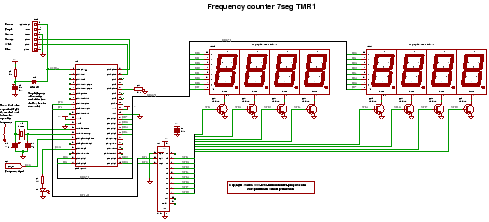
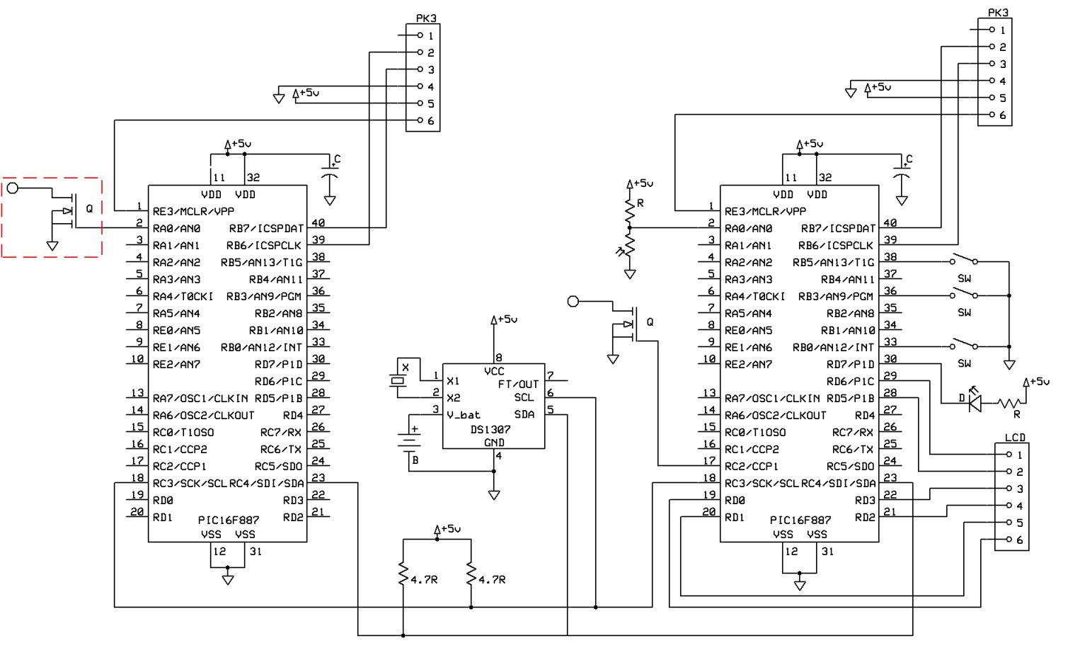
C code for a frequency counter circuit operating up to approximately 50 MHz, utilizing a multiplexed seven-segment display and employing Timer 1 to count the edges of the input signal. The frequency counter circuit described operates effectively within the range...
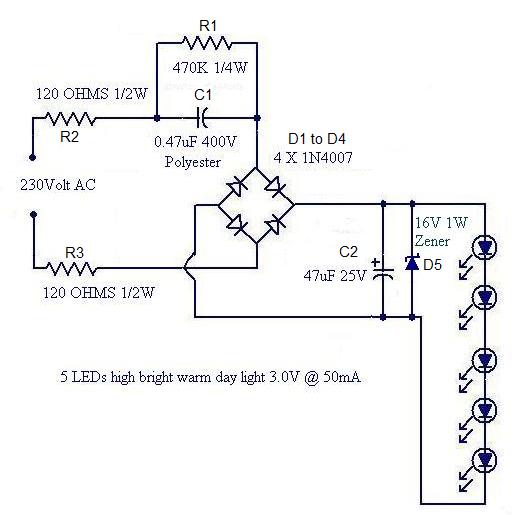
Convert a used CFL into a power-saving LED lamp circuit that consumes only 50mA. This gadget can be used in applications like a night light, table lamp, etc. The project involves redesigning a compact fluorescent lamp (CFL) to function as...
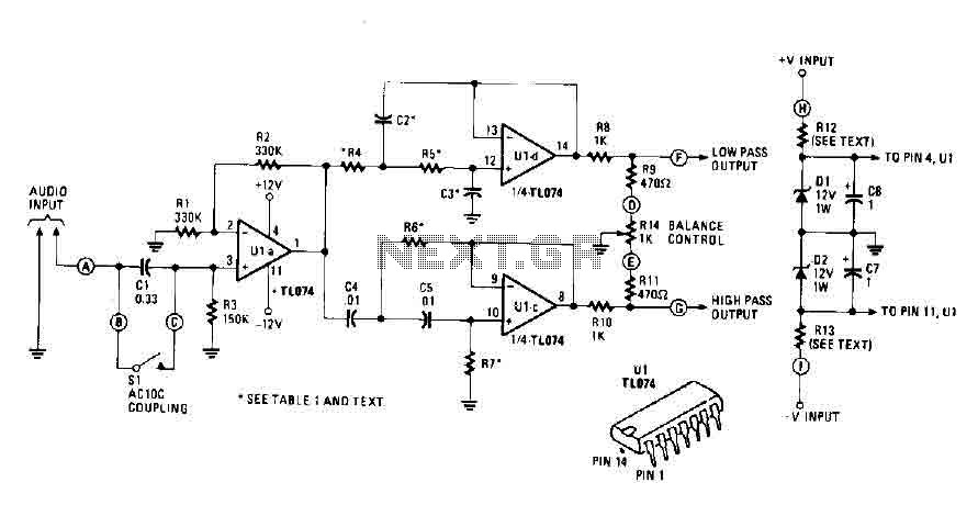
An audio source, such as a mixer, preamp, EQ, or recorder, is connected to the input of the Electronic Crossover Circuit. The signal can be either AC or coupled, depending on the setting of switch 51, which controls the...
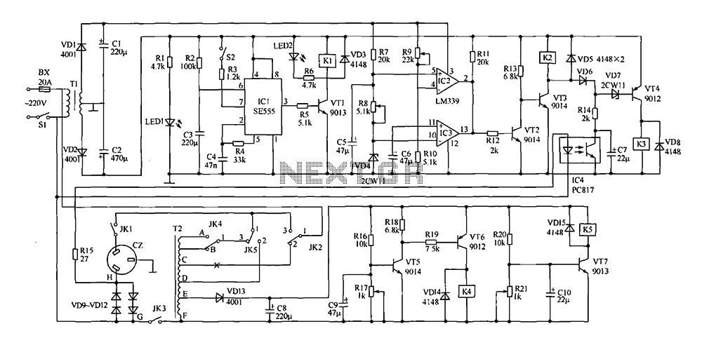
This document presents a power-saving voltage regulator circuit. In addition to its general function as a delay regulator, the circuit features: (1) an automatic voltage regulation capability for mains voltage within a range of 220V ±10%, allowing direct power...
A new post has been created regarding the Sunrise Word Clock project. The initial attempt to implement the circuit on a breadboard was unsuccessful, likely due to inadequate connections and suboptimal layout choices. The project has been rebuilt with...