
Saving voltage regulator circuit
The power-saving voltage regulator circuit is designed to efficiently manage voltage levels and minimize energy loss. It operates within a specified input voltage range of 160V to 270V, ensuring that the output remains stable at 220V ±10%. This stability is crucial for protecting sensitive electronic devices from voltage fluctuations that could lead to damage or reduced performance.
The circuit employs a feedback mechanism to regulate the output voltage, adjusting the voltage automatically when it exceeds safe limits. This is achieved through a combination of boosting and bucking techniques, allowing the circuit to either increase or decrease the voltage as necessary. This feature is particularly important in areas where mains voltage can vary significantly.
When the load is disconnected, the regulator automatically disengages from the power supply. This not only conserves energy but also prevents unnecessary wear on the components, enhancing the lifespan of the circuit. The design supports a maximum power output of 2500W, making it suitable for a variety of applications, from residential to industrial settings.
Component selection is critical for the performance of the circuit. The transistors VT4 and VT7 must have a higher rating than 150 to handle the load effectively, while diodes VD4 and VD7 are selected for their low forward voltage drop, ensuring efficient operation. The rectifier diodes VD9 to VD12 are rated for 10A, providing adequate current handling for the circuit's requirements.
Resistors used in the circuit are 1/8W carbon types, which provide stability and reliability. The electrolytic capacitor C4, rated at 25V, plays a vital role in smoothing out voltage fluctuations and ensuring a consistent output. The transformer T1, rated at two 12V and 3W, is essential for stepping down the voltage to the desired level while maintaining efficiency.
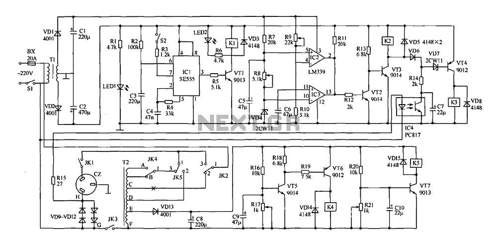
The relays K1 to K5, selected as SHA-T90 type 12V relays, are responsible for switching operations within the circuit, allowing for seamless integration of the regulator with the load. Overall, this power-saving voltage regulator circuit is a robust solution for maintaining voltage stability while minimizing energy loss, making it an essential component in modern electronic systems.Shown for the power-saving voltage regulator circuit. The regulator Besides general delay regulator function, its main features are: (1) mains voltage 220V 10% within the safe voltage range, automatic voltage regulator from the power supply, the power can be directly added to the load, the regulator itself eliminate losses. (2) When the mains voltage exceeds the safe range, automatically boost or buck. (3) When the load is zero, the regulator automatically from the power supply, eliminating the load loss. (4) Input voltage 160V ~ 270V, the output voltage of 220V 10% or less, in line with national standards.
Power 2500W.Component selection: VT4, VT7 value should be greater than 150. VD4, VD7 selected voltage value at about 4V genuine regulator; VD9 ~ VD12 chosen 10A rectifier diodes. Resistors are used (1/8) W carbon resistors. In addition to the capacitor C4 are selected voltage is 25V electrolytic capacitors. T1 use two-12V, 3W commercially available high-power transformers. K1 ~ K5 choose SHA-T90 type 12V relay. Note icon selected by the remaining elements.
Related Circuits
Very little extra circuitry is needed to do both forward and backward walking sequences along with a few other tricks. The PIC16F818 has a lot of features that work well in this situation. As you can see from the...
This two-transistor AM radio circuit is also referred to as a "mini-radio." It utilizes only two transistors and a few passive components, which makes it very easy to construct. The two-transistor AM radio circuit operates by utilizing a simple design...
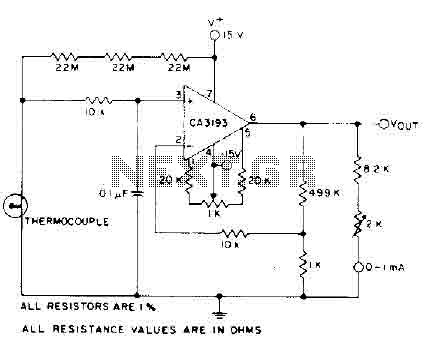
The circuit requires a 15-volt power supply and employs a precision operational amplifier, CA3193 BiMOS, to amplify the generated signal by more than 500 times. Three 22-megohm resistors are utilized to ensure a large-scale output in the event of...

A single pulse signal generating circuit is depicted, which utilizes switch contacts to create a digital signal for reset or stop functions. This one-shot pulse generating circuit operates as a non-synchronous differential circuit. The single pulse signal generating circuit, commonly...
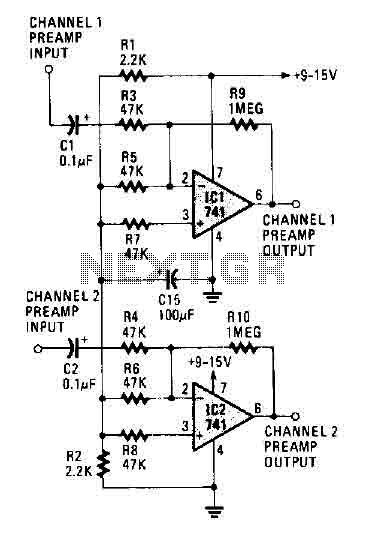
The circuit operates using two 741 operational amplifiers and achieves a gain exceeding 20 dB in each channel. Utilizing a higher-quality op-amp can improve the noise figure and bandwidth. Additionally, the circuit features a sharp roll-off at 20,000 Hertz. This...
VCR Camera Video Detector Switch Controller Circuit. This video detector switch controller circuit utilizes the video output from a VCR or camera to... This circuit functions as a video detector switch controller, designed to manage the video output from a...