
frequency counter circuit
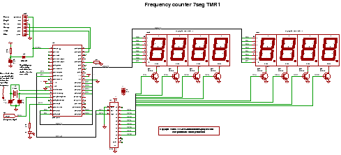
The frequency counter circuit described operates effectively within the range of up to 50 MHz. It utilizes a microcontroller that is programmed with C code to manage the counting of signal edges, which is crucial for accurately determining the frequency of the input signal. The circuit incorporates a multiplexed seven-segment display to visually represent the counted frequency, allowing for easy reading and interpretation of the data.
The core of the circuit relies on Timer 1 of the microcontroller, configured to operate in a mode that allows it to count the rising or falling edges of the input signal. This configuration is essential for capturing the frequency accurately. The microcontroller is programmed to increment a counter each time an edge is detected, with the count being displayed on the multiplexed seven-segment display.
The multiplexing of the display is achieved by rapidly switching between the segments of each digit, which creates the illusion of a steady display. This method is efficient and allows for the use of fewer pins on the microcontroller while still providing a clear output. The C code handles the timing of the multiplexing and ensures that the display is updated in synchronization with the counting process.
In summary, the frequency counter circuit integrates a microcontroller, Timer 1 for edge detection, and a multiplexed seven-segment display to provide an accurate and user-friendly method for measuring frequencies up to 50 MHz. The design and implementation of this circuit highlight the importance of precise timing and effective display management in electronic frequency measurement applications.and C code for a frequency counter circuit operating up to about 50MHz using a multiplexed seven segment display and uses timer 1 to count edges of the input signal.. 🔗 External reference
Related Circuits
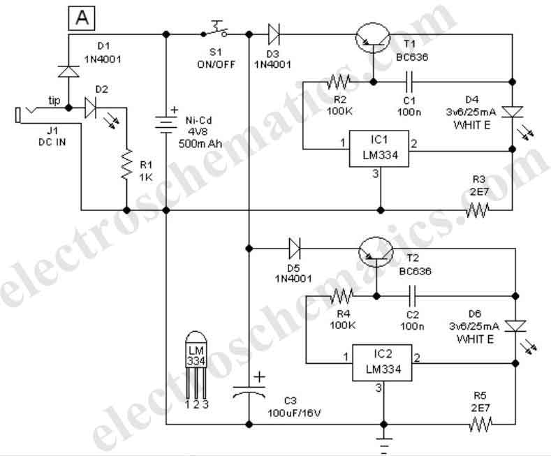
This easy-to-construct handy pen torch electronic circuit has a low component count and utilizes two power white LEDs for illumination. A low voltage (4.8V DC) supply is derived from a built-in rechargeable Ni-Cd battery pack and is converted into...
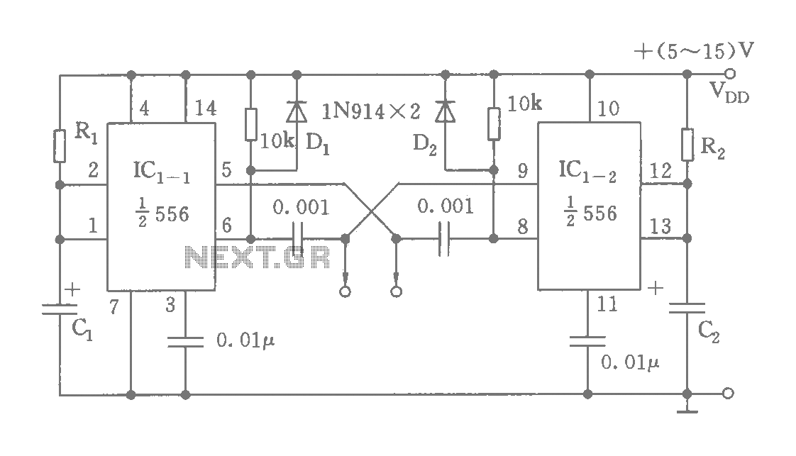
The circuit features a dual time base using a 556 timer, which comprises two synchronized multivibrators and two output clock signals. The output signals are synchronized with defined intervals, and the oscillation frequency can be adjusted by varying the...
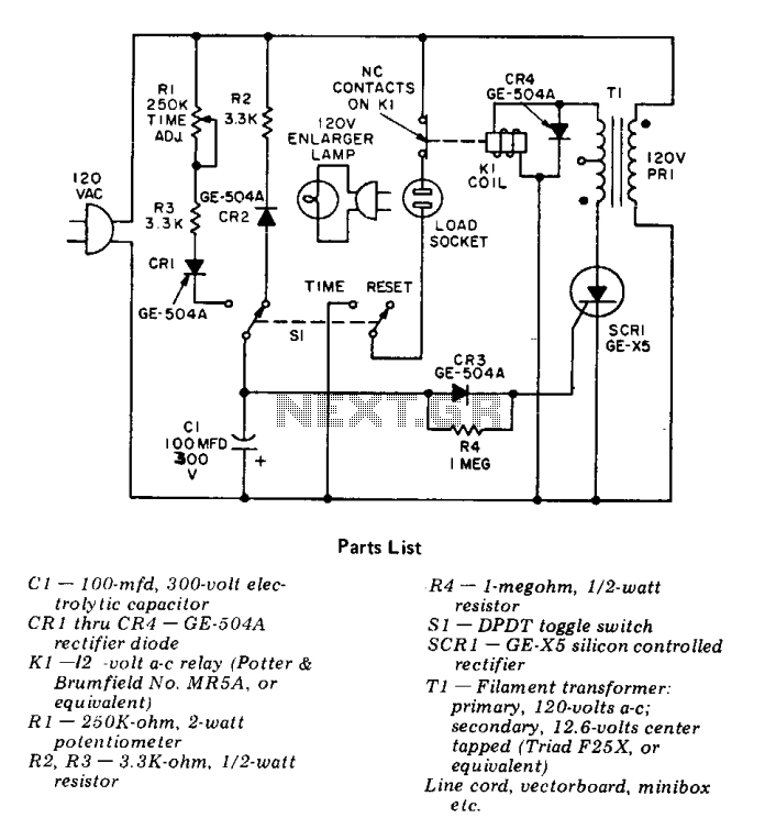
This precision solid-state time delay circuit features both delayed off and delayed on switch functions, which can be interchanged by simply swapping the relay contacts. The described time delay circuit is designed to provide precise control over the timing of...
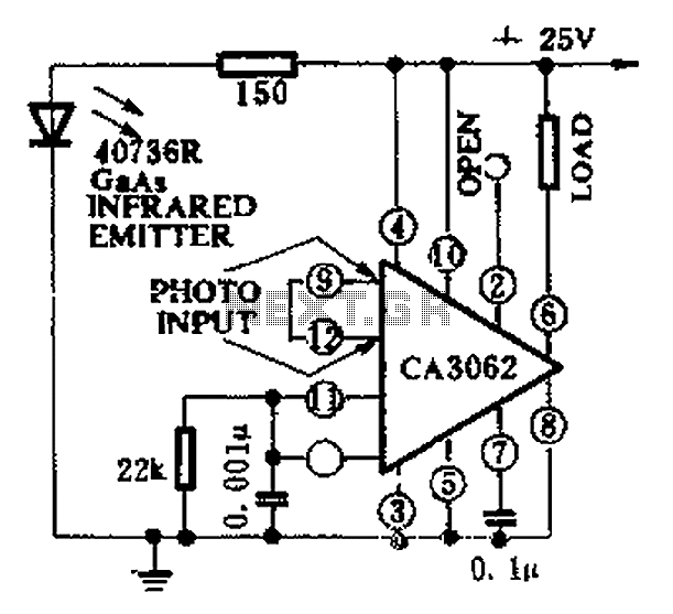
CA3062 is a combined photodetector and power amplifier that responds to the optical signal generated by the on/off output. The integrated circuit's transistor output saturation should be either on or off to prevent temperature rise in the silicon. When...
The RF power amplifier circuit described here utilizes the transistors 2SC1970 and 2N4427. This FM RF amplifier operates within the frequency range of 88-108 MHz, delivering an output power of approximately 1.3W from an input driver of 30-50mW. The...

An AC-coupled unity gain voltage follower operating on a single supply is illustrated. The voltage divider network consisting of resistors R1 and R2 provides a DC voltage equal to half the supply voltage to the non-inverting input of the...